


rev. 11/1/2016
CB-PMPS, manual.doc
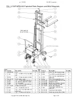
Copyright 2016 Vestil Manufacturing Corp. Page 8 of 23
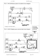
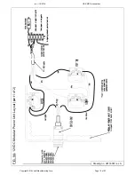
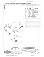
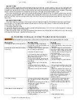
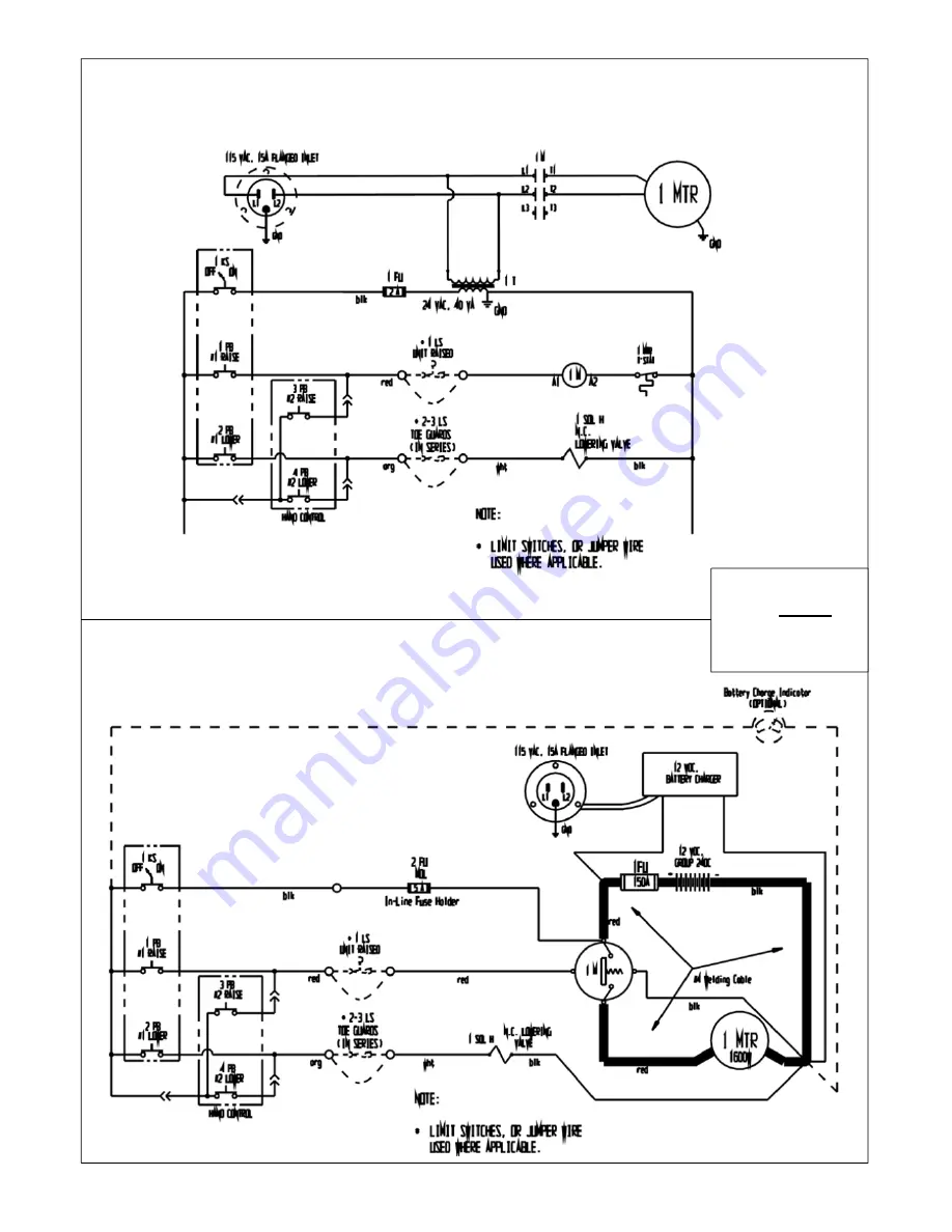
FIG. 5: 115VAC Modular power unit electrical circuit diagram
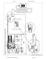
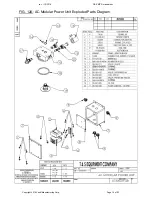
FIG. 6: 12VDC Modular power unit electrical circuit diagram
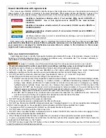
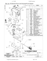
Disconnect
power
before
working on the
power unit!
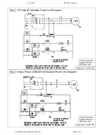
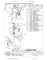
Drawing no. 99-124-026, Rev. D
Drawing no. 99-124-026, Rev. D


