Rev. 9/25/2017
HDC-450, MANUAL
Copyright 2017 Vestil Manufacturing Corp. Page 1 of 26
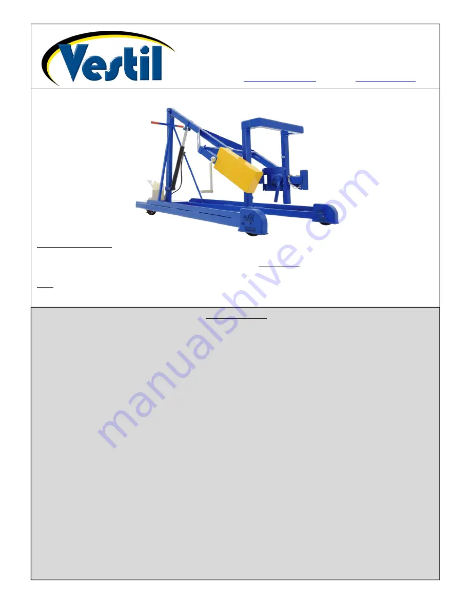
HDC-450 Series Manually-Propelled Hydraulic Drum Carriers Instruction Manual
Receiving instructions:
After delivery, remove the packaging from the product. Inspect the product closely to determine whether it
sustained damage during transport. If damage is discovered, immediately record a complete description of the
damage on the bill of lading. If the product is undamaged, discard the packaging.
Note:
The end-user is solely responsible for confirming that product design complies with all laws, regulations, codes,
and mandatory standards applied where the product is used.
Vestil Manufacturing Corp.
2999 North Wayne Street, P.O. Box 507, Angola, IN 46703
Telephone: (260) 665-7586 -or- Toll Free (800) 348-0868
Fax: (260) 665-1339
Web:
www.vestilmfg.com
e-mail:
info@vestil.com
Table of Contents
Signal Words………………………………………………………………………………............................................. 2
Hazards of Improper Use……...…………………………………………………………………………………..……… 2
Specifications (Dimensions, Net Weight, Capacity)……………………………………………………….…………… 3
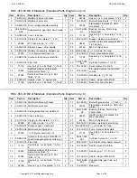
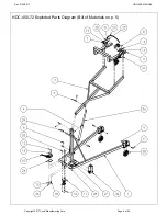
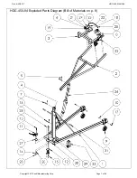
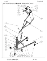
HDC-450-60 Exploded Parts Diagram and Bill of Materials.……………….……………....…………...……..…….. 4 - 5
HDC-450-72 Exploded Parts Diagram and Bill of Materials……………………………………….…………..……… 5 - 6
HDC-450-84 Exploded Parts Diagram and Bill of Materials…………….…………..…..…………………..………... 7 - 8
HDC-450-96 Exploded Parts Diagram and Bill of Materials………………….…………….……………..………….. 8 - 9
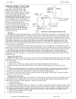
Hydraulic System - Foot Pump (Standard Units): Operation; Purging Air from the Pump;
Purging Air from the Cylinder……..……………………………………………………………………………………… 10
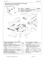
“Autoshifter” Foot Pump Exploded Parts Diagram and Bill of Materials………………...…………………………… 11 - 12
Hydraulic System Inspections and Maintenance……………….……………………………………………………… 12 – 13
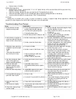
Troubleshooting (foot pump)……………………………………………………………………………………………… 13
Electrically Powered Drum Carriers (Options HDC-DC and HDC-AC)………………………………………………. 14
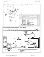
DC Modular Power Unit Exploded Parts Diagram and Bill of Materials……………………………………………... 14
DC Manifold Assembly Exploded Parts Diagram (Item 24 on p. 14)…..…………………………………………….. 15
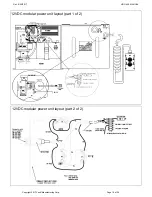
12VDC Modular Power Unit Electrical Circuit Diagram……………………………………………………….………. 15
12VDC Modular Power Unit Layout……………………..………………………………………………………………. 16
AC Modular Power Unit Exploded Parts Diagram and Bill of Materials……………………………………………… 17
Electrical Box and Manifold Exploded Parts Diagrams (Items 2 and 12 on p. 17)…………………………………. 18
115VAC Modular Power Unit Electrical Circuit Diagram………………………………………………………………. 18
115VAC Modular Power Unit Layout……………………………………………………………………………………. 19
Hydraulic Circuit Diagram (Powered Units; 01-127-010 Rev. C)…………………………………...………………... 19
Operating the Modular Power Unit (Raising & Lowering the Pivot Arm)……………..……………………………… 20
Using the Battery Charger (HDC-DC Units Only)………..…………………………………………………………….. 21
Lifting drums (standard and powered units)…………………………………………………………………………….. 22
Inspections & Maintenance……………………………………………………………................................................ 23
Troubleshooting guide (HDC-DC & HDC-AC)………………………………………………………………………….. 24 - 25
Labeling diagram……………………………………………………………………………………………..………..….. 25
Limited warranty…………………………………………………………………………………..……………………….. 26
*Unit shown is an HDC-450-60


