background image

TABLE OF CONTENTS


Rev. 5.24.2022 

LAD-RAF, MANUAL 

TABLE OF CONTENTS


Copyright 2022 Vestil Manufacturing  

Page 18 of 19 


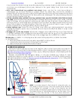
cross bar and the chain and snap hooks (if included with your ladder model). Confirm that the cross bar 

and chain are undamaged and securely fastened to the guard railing. Snap hooks should close 

automatically.  


Axle, axle receiver/back leg weldment and wheels

:  Make sure that the back leg weldment is 

undamaged,  e.g.  not bent, cracked, or warped. Check the wheels. They must not be  cracked or 

significantly worn. Wheels should be vertical (not angled towards or away from the ladder) and should roll 

smoothly. Make sure that the axle and the axle receiver are undamaged. The wheel retaining cotter pins 

must be securely fastened to the axle. 


All frame members (step weldment, back leg weldment, base supports, handrails) and all fasteners (bolts, 

nuts, pins)

: Inspect each frame member weekly for damage like excessive wear, warps, cracks, and other 

types of damage. All frame pieces should be square, rigid, and free of rust and corrosion. Remove rust 

with steel wool or a metal bristle brush and apply touch-up paint to the affected area. Check the areas 

where frame members are  bolted together. Check the areas around bolt holes  for warps, cracks, etc. 

Replace all parts that are damaged before using the ladder again.  


Square (rubber)  caps

:  Check the caps for cracks,  tears,  and wear. Install replacement caps before 

returning the ladder to service. Even a moderate amount of wear can affect the ability of a cap to resist 

sliding movement. 


Outriggers (11 and 12 step models)

: Examine the outriggers and confirm that they are securely fastened 

to the step weldment. Both outriggers should make solid contact with the ground, i.e. the ladder should 

not be able to wobble. Confirm that the caps on the outrigger legs are in satisfactory condition. 


Maintenance

: in addition to correcting issues discovered during inspections, maintain the ladder 

as described below.  


Clean the ladder to remove dirt and grime, especially from step surfaces. 


Lubricate the axle as necessary for the wheels to rotate freely. 


Apply touchup paint wherever the finish is chipped. 


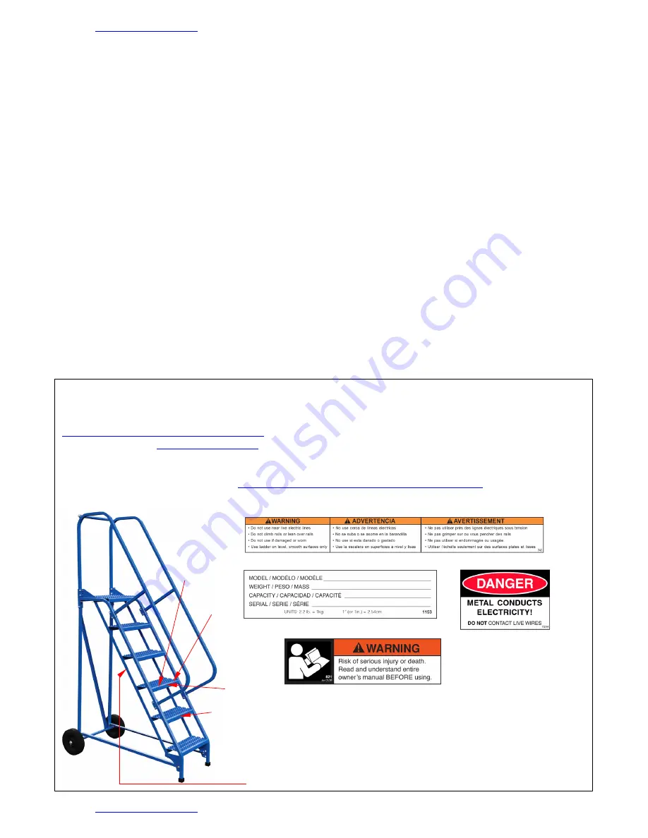
LABELING DIAGRAM


Each unit should be labeled as shown in the diagram. Label content and location are subject to 

change so your product might not be labeled exactly as shown. Compare the diagram below to your 

RECORD OF SATISFACTORY CONDITION

. If there are any differences between actual labeling and this 

diagram, contact 

TECHNICAL SERVICE

. 

Replace all labels that are damaged, missing, or not easily readable (e.g. faded). To order 

replacement labels or to inquire whether your unit is properly labeled, contact the technical service 

and parts department online at 

https://www.vestil.com/page-parts-request.php

  or by calling (260) 

665-7586 and asking for the Parts Department. 


B

: Label 1153 


C

: Label 729A 


A

: Label 740  


D

: Label 821 


NOTE:

  To provide access to this manual for all persons who use 

this ladder, a protected copy of the manual should be attached 

to the ladder. For example, a copy of the manual can be 

placed inside a transparent plastic pouch or folder that is tied to 

the ladder frame. An appropriate place to tie the folder to the 

frame is on the side rail next to the step where label 821 is 

applied. 

Summary of Contents for LAD-RAF Series

Page 1: ...line at https www vestil com page parts request php Electronic Copies of Instruction Manuals Additional copies of this instruction manual may be downloaded from https www vestil com page manuals php V...

Page 2: ...n 28 in 451 4 in 523 4 in 58 350 lb 120 2 lb LAD RAF 7 G 7 100 in 70 in 1613 16 in 28 in 511 2 in 601 8 in 58 350 lb 133 8 lb LAD RAF 8 24 G 8 110 in 80 in 239 16 in 341 4 in 573 4 in 663 8 in 58 350...

Page 3: ...ladder DO NOT increase the height of the platform or of a step by standing on other objects placed on the ladder Inspect the ladder as described in INSPECTIONS MAINTENANCE on p 17 18 DO NOT use the l...

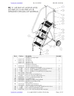
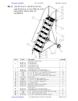
Page 4: ...6 in 18 UNC x 3 4 in HHCS 2 zinc plated bolt 4 6 44 112 006 Wheel axle 1 7 16 132 310 10 in x 21 2 in 16mm steel hub 2 8 65125 3 16 in x 11 2 in zinc plated cotter pin 2 9 99 024 027 1 in x 1 in 60 Du...

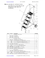
Page 5: ...3 5 16 in 18 UNC x 3 4 in HHCS 2 zinc plated bolt 4 6 44 112 006 Wheel axle 1 7 16 132 310 10 in x 21 2 in 16mm steel hub 2 8 65125 3 16 in x 11 2 in zinc plated cotter pin 2 9 99 024 027 1 in x 1 in...

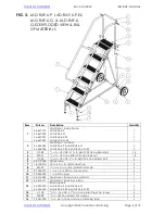
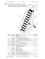
Page 6: ...3 5 16 in 18 UNC x 3 4 in HHCS 2 zinc plated bolt 4 6 44 112 006 Wheel axle 1 7 16 132 310 10 in x 21 2 in 16mm steel hub 2 8 65125 3 16 in x 11 2 in zinc plated cotter pin 2 9 99 024 027 1 in x 1 in...

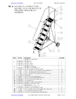
Page 7: ...3 5 16 in 18 UNC x 3 4 in HHCS 2 zinc plated bolt 4 6 44 112 006 Wheel axle 1 7 16 132 310 10 in x 21 2 in 16mm steel hub 2 8 65125 3 16 in x 11 2 in zinc plated cotter pin 2 9 99 024 027 1 in x 1 in...

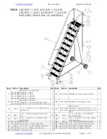
Page 8: ...053 5 16 in 18 UNC x 3 4 in HHCS 2 zinc plated bolt 4 6 44 112 007 Wheel axle 1 7 16 132 310 10 in x 21 2 in 16mm steel hub 2 8 65125 3 16 in x 11 2 in zinc plated cotter pin 2 9 99 024 027 1 in x 1 i...

Page 9: ...UNC x 11 2 in HHCS 2 zinc plated bolt 18 4 37021 5 16 in 18 zinc plated 2 nylon lock nut 22 5 11053 5 16 in 18 UNC x 3 4 in HHCS 2 zinc plated bolt 4 6 44 112 007 Wheel axle 1 7 16 132 310 10 in x 21...

Page 10: ...in 18 UNC x 3 4 in HHCS 2 zinc plated bolt 4 6 44 112 007 Wheel axle 1 7 16 132 310 10 in x 21 2 in 16mm steel hub 2 8 65125 3 16 in x 11 2 in zinc plated cotter pin 2 9 99 024 027 1 in x 1 in 60 Dur...

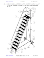
Page 11: ...nt back leg 11 step 1 3 11059 5 16 in 18 UNC x 11 2 in HHCS 2 zinc plated bolt 18 13 44 014 402 44 014 515 Base support LAD RAF 11 24 P LAD RAF 11 24 G LAD RAF 11 24 P EZ LAD RAF 11 24 G EZ 2 4 37021...

Page 12: ...v 5 24 2022 LAD RAF MANUAL TABLE OF CONTENTS Copyright 2022 Vestil Manufacturing Page 12 of 19 FIG 9 LAD RAF 12 24 P LAD RAF 12 24 P EZ LAD RAF 12 24 G LAD RAF 12 24 G EZ EXPLODED VIEW BILL OF MATERIA...

Page 13: ...assemble the ladder 1 2 crescent wrenches 1 2in or adjustable to 1 2in 2 Rubber mallet 3 Pliers preferably needle nose to bend arms of cotter pins 4 Proper work clothing eye protection gloves 5 Sturd...

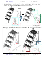
Page 14: ...he back leg weldment as shown below support tabs should face inwards Step 2 Fasten the base supports to the support brackets and support tabs with 5 16in 18 hardware as shown in the diagrams 5 16 in 1...

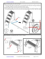
Page 15: ...p the plugs and caps into place b Insert the axle through the axle receiver of the back leg weldment c Then slide the wheels onto the ends of the axle Secure the wheels to the axle by inserting a cott...

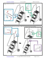
Page 16: ...e 16 of 19 Step 5 Attach the handrails Step 6 Install the handrail cross bar NOTE 12 step models also include a chain midrail Cross bar 3 8in flat washer 3 8in 16 x 13 8in hex cap screw Attach chain m...

Page 17: ...must solidly contact the ground The caps are provided to help the ladder resist movement during use Confirm solid contact between the entire bottom surface of each cap and the floor before climbing th...

Page 18: ...vement Outriggers 11 and 12 step models Examine the outriggers and confirm that they are securely fastened to the step weldment Both outriggers should make solid contact with the ground i e the ladder...

Page 19: ...lic pumps motor controllers and cylinders It also covers defects in original parts that wear under normal usage conditions wearing parts such as bearings hoses wheels seals brushes and batteries How l...

Reviews: