Rev. 5.24.2022
LAD-RAF, MANUAL
Copyright 2022 Vestil Manufacturing
Page 3 of 19
SIGNAL WORDS
SIGNAL WORDS in this manual draw the reader’s attention to important safety-related messages.
SAFETY INSTRUCTIONS
Vestil strives to identify foreseeable hazards associated with the use of its products, but no manual can address every
conceivable risk. Reduce risk by applying sound judgment whenever using this device. Acquire a copy of the latest
version of ANSI A14.7 (“A14.7” or the “Standard”). Apply all parts of the Standard that concern using, inspecting,
maintaining & repairing of the ladder.
Keep a copy of this manual with the ladder at all times, e.g.
inside a plastic
pouch attached to the frame.
Anyone who uses this ladder must be made aware that a copy of the manual is
available and where to find it.
If this product is used improperly or
carelessly, the user and/or bystanders might sustain serious
personal injuries or could even be killed. ALWAYS use the product properly:
•
Read & understand the entire manual before assembling, using, inspecting, or servicing the ladder.
•
DO NOT use this ladder unless you are in good health. NEVER use the ladder while under the influence of alcohol or
drugs, including prescription medication that affects balance, perception, or judgment.
•
DO NOT exceed the capacity/rated load. The total weight applied to the ladder (weight of the user plus tools, etc.)
must not be greater than the capacity. The capacity is provided on label 287. See
•
Wear appropriate footwear. DO NOT wear high-heeled shoes or footwear with smooth soles.
•
DO NOT use the ladder on uneven, sloped, or unstable surfaces. ONLY use the ladder on even, level surfaces.
•
Make sure that you will not contact overhead objects with either your body or with the ladder during use.
•
Avoid electrical shock! Take precautions to prevent any contact, or possible contact, with an energized, insulated
conductor (electrical line).
•
Remove foreign matter, e.g. mud, from your shoes
before
walking on the ladder. Only wear slip-resistant shoes.
•
Only stand on the steps or the platform. DO NOT climb onto the railing. DO NOT slide on the railing.
•
DO NOT access, or egress from, any step or the platform from another elevated surface unless the ladder is positively
secured against movement.
•
ALWAYS face the stairs and use the handrails while ascending and descending the ladder.
•
DO NOT increase the height of the platform or of a step by standing on other objects placed on the ladder.
•
Inspect the ladder as described in
on p. 17-18. DO NOT use the ladder unless it is in
Satisfactory Condition
. ONLY use manufacturer-approved replacement parts when repairs are necessary.
•
DO NOT use the ladder if the caps on the front legs are significantly worn. See applicable
Caps should prevent the ladder from sliding. If either or both caps are too worn to function properly, replace them
before using the ladder again.
•
ONLY use the ladder to access elevated working positions. DO NOT use the ladder for any other purpose. DO NOT
store materials and/or equipment on the steps or platform. Always unload the ladder before leaving it unattended.
•
DO NOT position an occupied ladder in front of a door unless that door is secured in an open position, is locked, is
attended, or is barricaded.
•
DO NOT lean, or reach, over the handrails or guardrails of the ladder. Position the ladder as close to the work as
possible. Reposition the ladder to prevent overreaching. Overreaching could cause instability and result in a fall.
•
Avoid sudden shifts while on the ladder. DO NOT push, pull, or lean on the handrails or guardrails.
•
DO NOT skip steps. Climb the ladder one step at a time.
•
DO NOT attempt to move the ladder while someone is using it. The ladder must be unoccupied before it is moved.
•
DO NOT use the ladder to transport people or objects. DO NOT ride on the ladder
•
DO NOT remove or obscure any label. Each label must be readable, undamaged, and present in the appropriate
location. See
on p. 18.
•
DO NOT modify this ladder! Unauthorized modifications automatically void the
(p. 19)
and might
make the ladder unsafe to use.
•
Only locking fasteners should be used. During assembly, confirm that there are only locking nuts. Contact
(see cover page) if you find non-locking nuts. Lock nuts can only safely be used once. Discard used lock nuts
and install new lock nuts after unfastening any connection.
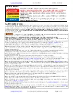
DANGER
Identifies a hazardous situation which, if not avoided, WILL result in DEATH or
SERIOUS INJURY. Use of this signal word is limited to the most extreme situations
.
WARNING
Identifies a hazardous situation which, if not avoided, COULD result in DEATH or
SERIOUS INJURY.
CAUTION
Indicates a hazardous situation which, if not avoided, COULD result in MINOR or
MODERATE injury.
NOTICE
Identifies practices likely to result in product/property damage, such as operation
that might damage the product
.
!
!
!


