background image

Table of Contents


Rev. 3.19.2020 

LAD-TRN MANUAL 


Table of Contents


Copyright 2020 Vestil Manufacturing Co. 

Page 8 of 12 


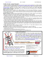
ASSEMBLY INSTRUCTIONS 

  Improper or incomplete assembly might result in a ladder that is unsafe to use. 

  Visually inspect all  ladder  components 

prior to assembly

.  Look at each part of the ladder immediately after you 

receive the package from the shipper.  Determine whether damage occurred during shipping. DO NOT assemble or use 

the  ladder stand  if you notice any  damage, especially to the step weldment, back leg weldment, base supports, or 

handrails.  Using a damaged component could lead to ladder collapse and result in serious personal injuries. 

  While assembling this ladder, confirm that only locking fasteners are provided, i.e.  only locking nuts. Contact 

TECHNICAL SERVICE

 (p. 1) if you find non-locking nuts. Only lock nuts should be used. However, lock nuts can only 

safely be used once. Discard the used lock nut and install a new lock nut after unfastening a connection 

  DO NOT assemble the ladder by yourself.  At least 2 people are needed for assembly. 

  Read the entire instruction manual before assembling this ladder. 

  DO NOT use the ladder if a wheel is damaged. Damaged wheels might cause the ladder to wobble or tip when used. 

The following tools are necessary to assemble the ladder: 2 crescent wrenches (

5

/

16

” and 

3

/

8

”); Rubber mallet. 


NOTE:

 Numbers in diagrams and in parentheses () correspond to part numbers in the exploded views on p 4-7. 


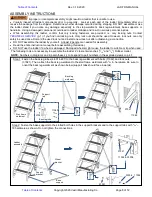
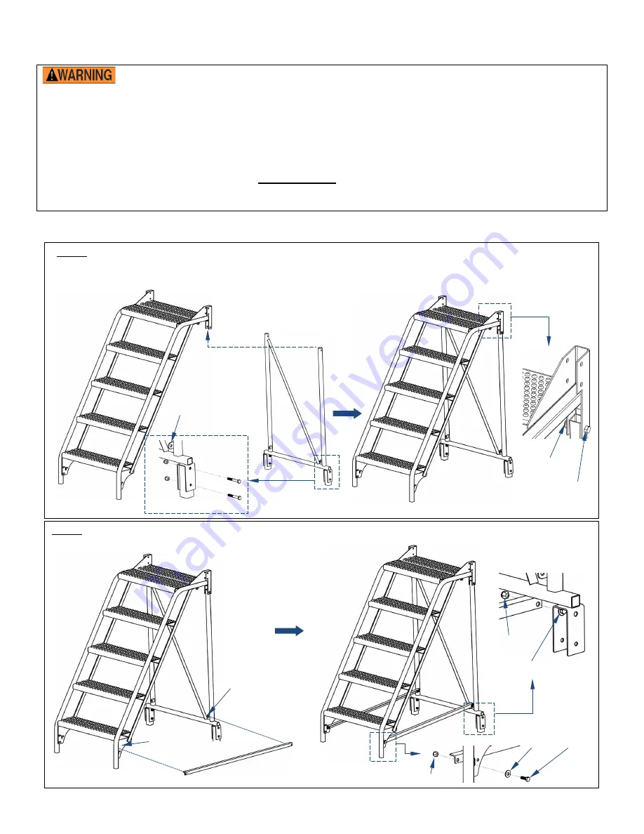
Step 1:  Fasten the back leg tubes (44-014-487) to the back leg weldment with bolts (11062) and lock nuts 

(37021). Then, attach the back leg weldment to the stair frame weldment with 

5

/

16 

in. hardware. Be sure to 

orient the back leg weldment as shown below (support tabs should face inwards). 


  Step 2: Fasten the base supports to the slotted bolt holes in the support brackets and to the support tabs with 

5

/

16

”–

18 hardware as shown. Do not tighten the connections. 


11060


Back leg 

weldment 

Stair frame 

weldment 

37021


Ladder 

assembly 

Support 

tab 

Wheel 

bracket 

Support 

bracket 


Base 

support 


37021 

11055 & 33006 


37021 

33006    11055 

11060 

37021 

Back leg tube 

Wa
ll 

Summary of Contents for LAD-TRN Series

Page 1: ...For answers to questions not addressed in these instructions and to order replacement parts labels and accessories call our Technical Service and Parts Department at 260 665 7586 The department can al...

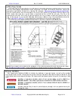
Page 2: ...t TECHNICAL SERVICE Contact information is provided on the cover page of this manual The following is an exemplar specifications document In this case it shows a LAD TRN 60 4 G NOTE If your model is n...

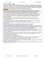
Page 3: ...climb on the railing DO NOT slide on the railing DO NOT access or egress from any step from another elevated surface unless the ladder is positively secured against movement ALWAYS face the stairs and...

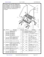
Page 4: ...514 300 44 514 301 Weldment back leg 26 step 2 step LAD TRN 2 P G 3 step LAD TRN 3 P G 4 step LAD TRN 4 P G 1 1 1 15 11062 Hex bolt 2 HHCS zinc plated 5 16 18UNC x 21 4 4 16 11107 Hex bolt gr A zinc f...

Page 5: ...4 16 11107 Hex bolt gr A zinc finish 3 8 16x11 4 2 3 44 514 313 Weldment frame caster tilter 2 17 11113 Hex bolt gr A 3 8 16x21 2 2 4 44 514 314 Weldment frame back platform 1 18 33006 Flat washer zi...

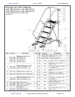
Page 6: ...4 300 Weldment back leg 26 step 2 step LAD TRN 60 2 P G 3 step LAD TRN 60 3 P G 1 1 15 11062 Hex bolt 2 HHCS zinc plated 5 16 18UNC x 21 4 4 16 11107 Hex bolt gr A zinc finish 3 8 16x11 4 2 3 44 514 3...

Page 7: ...16 11107 Hex bolt gr A zinc finish 3 8 16x11 4 2 3 44 514 313 Weldment frame caster tilter 2 17 11113 Hex bolt gr A 3 8 16x21 2 2 4 44 514 314 Weldment frame back platform 1 18 33006 Flat washer zinc...

Page 8: ...ock nut after unfastening a connection DO NOT assemble the ladder by yourself At least 2 people are needed for assembly Read the entire instruction manual before assembling this ladder DO NOT use the...

Page 9: ...Attach the handrails Ladder assembly 1 x1 square cap 99 024 027 Insert plug 99 025 025 Cross brace Handrail 11060 37021 1 black plastic plug 99 025 025 1 5 x1 5 square cap 99 024 028 1 5 black plasti...

Page 10: ...ners and users If any content in this manual conflicts with any mandatory provision s in the Standard apply the provision s from the Standard Vestil encourages you to immediately contact TECHNICAL SER...

Page 11: ...ch frame member for damage like excessive wear bends and cracks All frame pieces should be square rigid and free of rust and corrosion Remove rust with steel wool or a metal bristle brush and apply to...

Page 12: ...ulic pumps motor controllers and cylinders It also covers defects in original parts that wear under normal usage conditions wearing parts such as bearings hoses wheels seals brushes and batteries How...

Reviews: