Rev. 7/14/2021
LLCB-202058 MANUAL
Copyright 2021 Vestil Manufacturing Co.
Page
5
of
8
NATIONAL STANDARDS
This product is a manually propelled high lift truck. The Industrial Truck Standards Development
Foundation (ITSDF) publishes national standard ANSI/ITSDF B56.10 (the “Standard”) on its website
). The standard is freely downloadable at
http://www.itsdf.org/cue/b56-standards.html
Before putting the unit into service, acquire a copy of the Standard and apply all recommendations in Part
II: For the User. If instructions provided in this manual conflict with instructions in the Standard, then you
should apply the instructions in the Standard. Vestil encourages you to immediately contact
TECHNICAL
SERVICE
to report any differences between instructions in this manual and the Standard.
USING THE LIFTER
This product is a manually-propelled high lift truck of the sort describes in American national standard
ANSI/ITSDF B56.10 (“B56.10” or the “Standard”). Vestil recommends that the owner of this product acquire a
copy of the latest revision of B56.10, which is available at no cost through the ITSDF website (
).
The copy, along with this manual, should be available to all persons who use this product. Instructions in this
manual are meant to
complement
the information provided in
Part II – For the User
of the Standard.
ONLY use this device after completing the operator training program in B56.10, sections 4.17 and 4.18.1-4.
•
Develop safe working habits and an awareness of hazardous conditions occurring or present during
operation of the lifter.
•
Inspect the area where the lifter will be used
before each use
to identify unusual operating conditions.
Implement additional safety precautions as conditions require. Conditions might include:
1. Irregularities in the floor/surface.
2. Debris or other obstructions on the floor/surface.
3. Unsound surfaces or surfaces that cannot support your weight plus the weight of the lifter and a full
capacity load.
•
Perform the following
function test before each use
:
1. Raise and lower the platform and confirm normal operating condition of the lift mechanisms.
2. Test the casters/wheels: wheels should roll smoothly, should not be severely worn, and should be
rigidly fastened to the frame of the lifter.
Use the lifter only if it is in
, p. 7.
Step 1
: Grasp the handle with both hands. Walk behind the lifter and keep your feet away from the
wheels. ONLY use the lifter on even, level, concrete surfaces.
Step 2
: Move the lifter to load.
Apply the floor lock by firmly
pressing down on the lock lever.
Confirm that the foot pad of the
floor lock solidly contacts the floor
by trying to push the lifter. The
lifter should
resist
forward/backward movement
while the lock is applied. The floor
lock will not
prevent
movement.
Press lock lever down to
engage floor lock
Lift to vertical position
(shown) to disengage
floor lock
Foot pad of floor lock
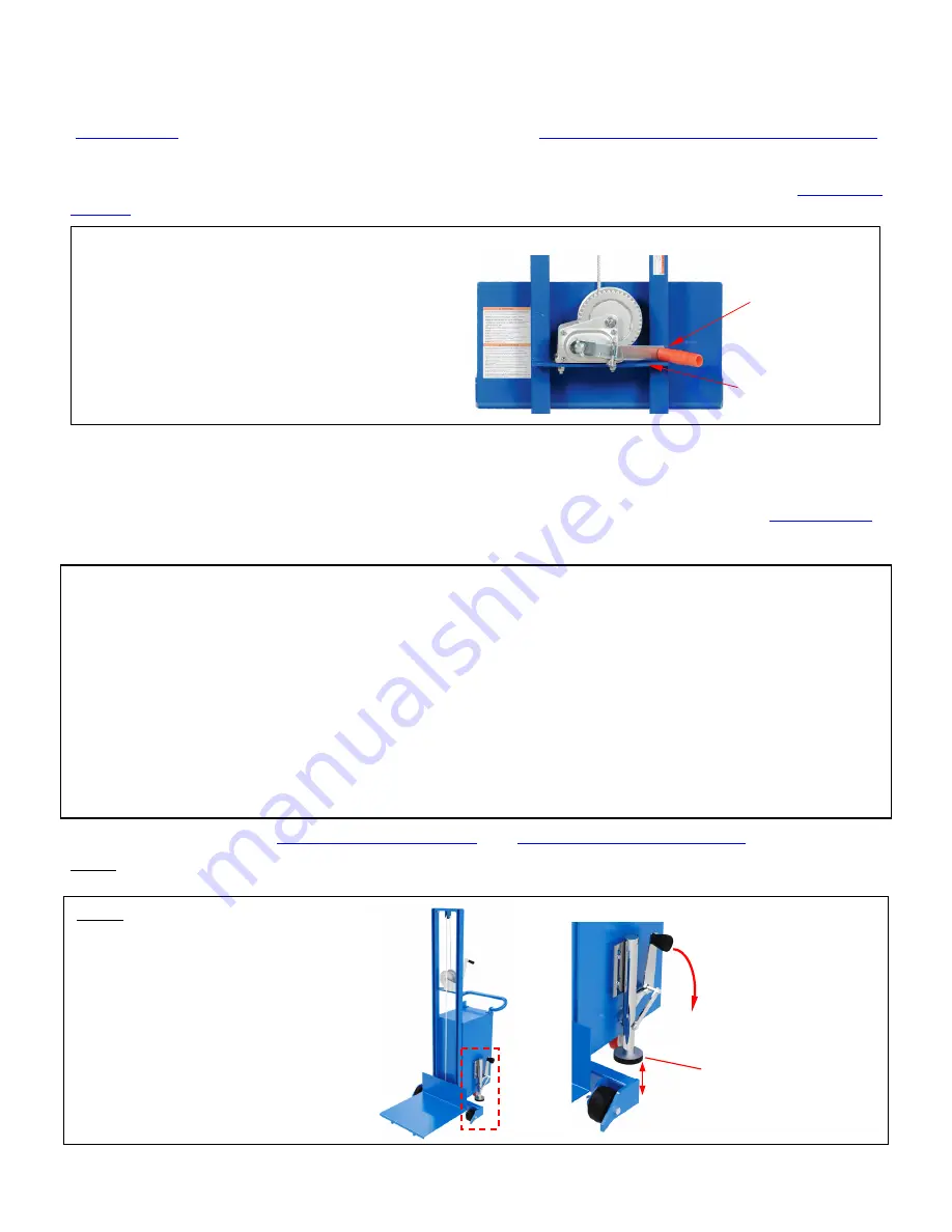
RAISING AND LOWERING THE PLATFORM
To raise and lower the platform, the lifter is
equipped with a manual winch. Raise the
platform by rotating the handle clockwise. The
platform rises ~1 inch with each rotation. Lower
the platform
by
turning
the handle
counterclockwise. Lay the handle on the winch
mounting bracket as shown when the platform is
elevated.
Rest winch handle
on winch mounting
bracket whenever
platform elevated
Winch mounting
bracket


