6/10/2021
LM-HP MANUAL
Vestil Manufacturing
Page
4
of
6
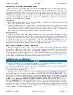
INSTALLING & USING THE ATTACHMENT
This product is a fork attachment subject to Federal OSHA Rule
The Rule states that you must request that either the manufacturer of your fork truck, or a
professional engineer, determine how using the lifter attachment will affect the capacity,
operation, and maintenance of your fork truck. Truck data plates, tags, labels, etc. must be
changed accordingly. The truck should also be marked to identify the attachment and to
display the approximate weight of the truck and attachment combination at maximum
elevation with load laterally centered.
Installation
1)
Adjust the positions of the forks on the fork carriage to align with the fork receivers; then slide
the unit onto the forks. Keep the forks level.
2)
Attach the safety strap to the fork carriage of your lift truck. Wrap the safety strap around the
fork carriage. Attach the hook (at the free end of the strap) to the safety strap. The strap must
be wrapped around the carriage a sufficient number of times so that there is no slack in the
strap. The strap must prevent the unit from sliding forward on the forks.
Using the Device
Adjust the position of the fork truck to vertically and horizontally align the lifting hook with
the center of gravity of the load. Connect the load to the hook via appropriate rigging. The
weight of the load must not exceed the capacity of the hook. [NOTE: Capacity appears on
the surface of the hook. It is also displayed on tag 1054. See
Connect the load to the hook to minimize load swing when the load is lifted off of the ground.
Swinging loads might cause injuries and/or could damage equipment.
RECORD OF SATISFACTORY CONDITION
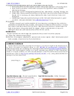
Before putting the unit into service, make a record of its condition. Photograph both sides of
the device. Take close range photos of the hook, shackle, safety strap, and strap hook.
Photograph both sides of tag 1054. See
openings of both hooks. Collate the photos and written descriptions into a single file. This file is
a record of the product in satisfactory condition. Compare the results of each inspection to
this RECORD to determine whether the unit is in satisfactory condition.
INSPECTIONS & MAINTENANCE
NOTICE
Proper use, maintenance, and storage are essential for this product to function properly.
o
Inspect the unit as instructed and as frequently as instructed.
o
Inspect and maintain the product as recommended in the current revision of ANSI/ITSDF
B56.1, as well as all instructions in this manual.
o
Store the unit in a dry location.
Compare the results of each inspection to the
RECORD OF SATISFACTORY CONDITION
to
determine whether the unit is in satisfactory condition. DO NOT use the lifter unless it is in
satisfactory condition. Only use manufacturer-approved replacement parts to restore the unit
to satisfactory condition.
Never make temporary repairs of damaged or missing parts
.
DON’T
GUESS!
If you have any questions about the condition of your lifter, contact the
TECHNICAL
SERVICE
department.
The phone number is provided on the cover page of this manual. Purely
cosmetic changes, such as chipped paint, are not changes from satisfactory condition.
However, touchup paint should be applied to all areas where the finish is damaged as soon as
the damage occurs. Exposed metal rusts. If left exposed, rust could compromise the soundness
of the metal and create a safety hazard.


