Operation:
The speed control knob should already be in the “Stop” position, but if not, turn the knob to “Stop”.
Insert a key (two keys are enclosed inside packaging with this manual) into the slot in the key switch, and turn the key
to the “On” position. The battery charge/capacity display (see FIG. 6) will illuminate when system power is turned on
(see Fig. 6 on p. 3). The red LED will flash if the batteries require recharging.
Select the desired speed setting: low or high with the speed selection knob. To propel the cart, grasp the handle and
press the self-propulsion lever and handle together.
Slowly
and gradually release the lever to stop the cart.
Turn the speed selection knob to “Stop” before the cart is left unattended.
The “Direction governing lever” prevents accidental operation in reverse. To use the lever, pivot it over the operation
control panel as shown in FIG. 6. Always use the lever when operating the cart in forward (low or high). To operate
the cart in reverse, flip up the lever, turn the speed selection knob to “Reverse”, and then press the self-propulsion
lever and handle together.
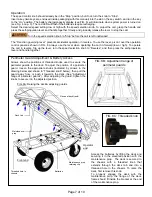
Perimeter Guard Adjustment & Battery Access
FIG. 8B: Adjustment range of
perimeter guards
Maintenance
prop
Arrows show the positions of threaded knobs used to secure the
perimeter guards to the deck. To adjust the position of a perimeter
guard, loosen the appropriate knobs (indicated by arrows in the
drawing below and shown in “Threaded knob” below); then pull the
guard away from, or push it towards, the deck (See “Adjustment
range of perimeter guards”). After adjusting the guard, tighten the
knobs to secure it in the adjusted position.
FIG. 8A: Raising the deck & adjusting guards
Threaded hole in
chassis
Deck tab
FIG. 8C: Threaded knob
Maintenance prop
retaining clip
Flange of deck fram
e
Operator
end
Front end
Access the batteries by lifting the deck and
securing it in the elevated position with the
maintenance prop. The deck is secured to
the chassis with a threaded knob that
extends through the deck tab and into a
threaded hole in the chassis. To raise the
deck, first remove this knob.
To properly engage the deck with the
maintenance prop, the flange of the deck
frame should fit inside the bracket at the end
of the maintenance prop.
Batteries
Page 7 of 10
Summary of Contents for OROAD-400
Page 5: ......


