background image

03/10/03 

rev. 3/6/2017 

   WP, MANUAL 

                                   Copyright 2017 Vestil Manufacturing Co. 


Page 

14

 of 

16


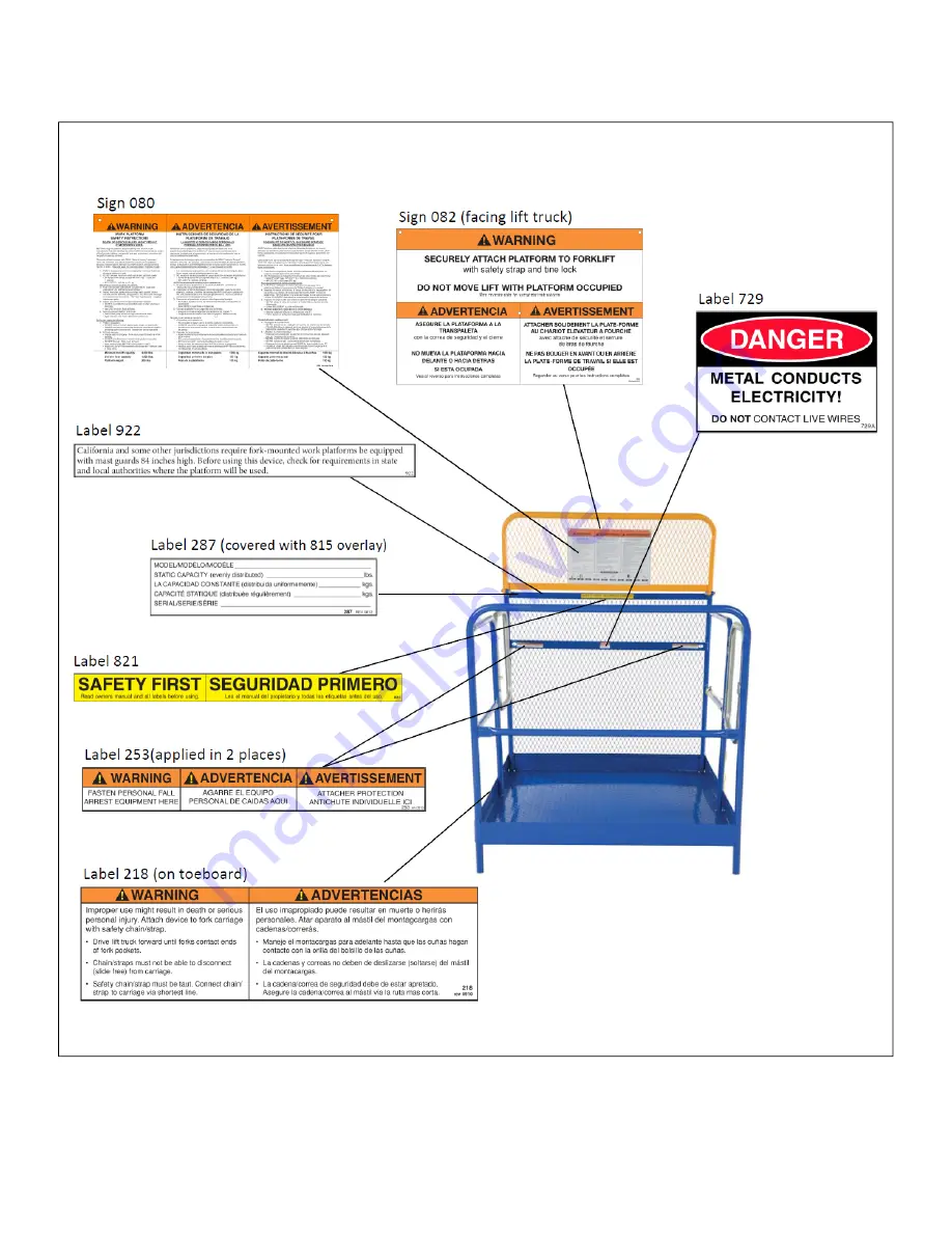
Labeling diagram: 

The work platform should always be labeled as shown in the diagram below. Replace every label that becomes 
damaged or unreadable. 


WP-series platforms:


Summary of Contents for SP Series

Page 1: ...astener order 13 Limited Warranty 16 Receiving instructions After delivery remove the packaging from the product Inspect the product closely to determine whether it sustained damage during transport If damage is discovered record a complete description of the damage on the bill of lading If the product is undamaged discard the packaging NOTES Compliance with laws regulations codes and non voluntar...

Page 2: ...P 4848 DD 48 x 48 122 x 122 cm 24 61cm 60 152cm 288 131kg WP 4848 DD FF 48 x 48 122 x 122 cm 24 61cm 60 152cm 304 138kg WP3636 84B DD 36 x 36 91 x 91 cm 16 41cm 84 213cm 246 112kg WP 3648 84B DD 36 x 48 91 x 122 cm 16 41cm 84 213cm 259 118kg WP 4848 84B DD 48 x 48 122 x 122 cm 24 61cm 84 213cm 300 136kg WP 4848 FF 84B DD 48 x 48 122 x 122 cm 24 61cm 84 213cm 316 144kg WP 3737 FD FOLD DOWN MODEL 37...

Page 3: ... Large 5ft 8in 5ft 11in 173 180 cm Small Medium Large X Large XX Large XXX Large 6ft 6ft 3in 183 191 cm Medium Medium Large X Large XX Large XXX Large 6ft 3in and Taller 191cm and taller Large Large X Large X Large XX Large XXX Large Employers are responsible for instructing employees to use the product properly see OSHA standard 1910 178 and 1993 letter of interpretation accessible at http www os...

Page 4: ...ons 29 CFR 1910 178 accessible at http ecfr gpoaccess gov cgi t text text idx c ecfr sid 96a878227f273aa6ec3cea186e1c142b rgn div8 view text node 29 5 1 1 1 8 14 37 3 idno 29 In addition to requirements by law work platform users should conform to the following Contact the manufacturer of your lift truck to verify that the truck is capable of safely handling the fully loaded platform see NOTE on p...

Page 5: ...ged WP series gate s are spring actuated and should automatically close when released If a gate s does not automatically close replace the spring before resuming use of the platform 4 Handrails check the rails rail welds and points of attachment to the platform for bending warping and cracking 5 Lanyard attachment points check the anchorage weldment see diagrams on p 9 and points of attachment to ...

Page 6: ...514 128 14 514 125 14 514 128 14 514 126 14 514 129 1 8 13 x 1 1 2 HHCS 2 zinc plated bolt 11209 2 9 13 zinc plated hex nut 36110 2 10 13 x 2 HHCS zinc plated bolt 11211 2 Nylon safety strap 08 145 028 1 Complete tine lock assembly 14 537 007 1 9 8 FIG 1 WP series Diagram Parts List Close up of tine lock assembly Item no Part no Description Quantity 1 14 112 001 5 8in x 9 1 2in pin 2 2 45286 1 8in...

Page 7: ...6 5 41 9cm 18 0 45 7cm WP series center of gravity C O G Mast guard If the mast guard is improperly fastened it cannot adequately protect platform occupants Therefore make sure that hinge fasteners circled in the drawings are tightened to 35ft lb of torque Retighten the connection to 35 ft lb whenever 1 The work platform is taken out of storage Raise the upper portion of the mast guard and then Ti...

Page 8: ...rriage with the securing chain and capture the heel of the fork with the tine lock underneath the corner of the platform as shown in the drawings below NOTE The safety strap is the primary safety mechanism and must be used each time the work platform is used To use the safety strap properly attach the device to the fork truck carriage as instructed in Step 2 on p 9 Each work platform also includes...

Page 9: ... commit product misuse and bear sole responsibility for the consequences To reduce the likelihood of harmful consequences Both the WP series and SP series products are medium duty rated platforms ONLY use with sit down rider high lift fork trucks having a minimum load capacity of 3 000 pounds at a 24 load center ALWAYS review the Warnings and Safety Instructions on p 1 before each use ALWAYS apply...

Page 10: ...utomatically returns to the closed position Push outwardly on the gate to confirm that it is locked Models having a gate on both sides WP DD after entering this work platform from either side let go of the gate to allow it to close automatically Confirm that both gates function properly i e fully and automatically close before proceeding to use the platform Model SP 175 enter the platform and then...

Page 11: ...rm to the tines of the fork lift The nylon strap is an essential safety enhancing feature designed to connect the work platform to the carriage of a fork lift Improperly connecting the nylon safety strap to either the platform or the fork lift might eliminate the safety benefit a Drive the forklift tines into the fork pockets then secure the platform to the fork lift with the tine lock see Step 1 ...

Page 12: ...f foreign material inside the posts 2 Raise the work platform high enough to allow the casters to be inserted into the bottom of each of the four posts 3 Examine each caster verify that each has a plastic spacer a black rubber expansion sleeve and a knurled nut as shown in Figure A 4 Hold onto the 2 tightening hub at the top of the caster rig with your hand and snug the knurled nut against the top...

Page 13: ...nside surface of the mast guard Proper fastener order is shown in Fig 11 Use Instructions a To operate the fork truck without platform attached plug the FTJB jumper cord into the socket in the FTJB connect the fork truck junction box to itself b Work platform attached unplug the jumper cord from the FTJB socket then plug the male plug of the coil cord into the socket of the FTJB Pull the E stop bu...

Page 14: ... MANUAL Copyright 2017 Vestil Manufacturing Co Page 14 of 16 Labeling diagram The work platform should always be labeled as shown in the diagram below Replace every label that becomes damaged or unreadable WP series platforms ...

Page 15: ... MANUAL Copyright 2017 Vestil Manufacturing Co Page 15 of 16 Labeling diagram The work platform should always be labeled as shown in the diagram below Replace every label that becomes damaged or unreadable SP series platforms ...

Page 16: ...he warranty covers defects in the following original dynamic components motors hydraulic pumps electronic controllers switches and cylinders It also covers defects in original parts that wear under normal usage conditions wearing parts such as bearings hoses wheels seals brushes and batteries How long is the warranty period The warranty period for original dynamic components is 90 days For wearing...

Reviews: