background image

TABLE OF CONTENTS


Rev. 3/7/2022 

VST-4-Y, MANUAL 


TABLE OF CONTENTS


Copyright 2021 Vestil Manufacturing Corp.                                                      Page 7 of 10 
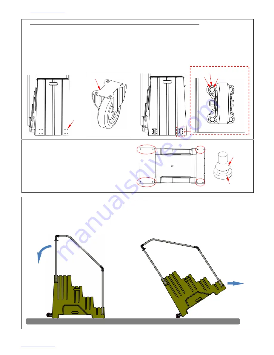
4.


Fasten casters (16-132-197) to the back of the steps with 1/4” hardware 

a.


Put a 1/4” flat washer (33004) followed by a 1/4” lock washer (33618) onto each of 8 

bolts (11007). Bolts are 1/4”-20 x 1.25”. 

b.


Eight (8) pilot holes are provided in the rear wall of the steps.  

c.


Fasten each caster to the rear wall with four sets of bolts (11007), flat washers (33004), 

and lock washers (33618). Insert the bolts through the bolt holes in the caster mounting 

brackets and wind them into the pilot holes. NOTE: Expanding insert nuts (99-145-196) 

are preinstalled in the pilot holes. 


5.


Install the molded rubber feet (14-145-179) 

a.


Lay the steps on the left or right side. 

b.


Locate the 8  openings that receive 

the feet (circled). 

c.


Press a foot into each opening.  The 

yellow  floor  material  of the steps 

should seat between the floor  pad 

and the retaining ring. 


Rear view 


Mounting bracket 


Caster 

Pilot 

holes 


Bolt 

Lock washer 


Retaining 

ring 

Floor pad 


USING THE STEPS 

  Only use the steps on level, even ground. Make sure that all (8) molded feet make solid 

contact with the ground before standing on the steps. 

  Move the steps by grasping the handrail posts at the top of the steps. Pull the handrails 

towards you to tip the steps onto the casters. Push the steps to the desired location. 


Flat washer 

Summary of Contents for VST-4-Y

Page 1: ... to questions not addressed in these instructions and to order replacement parts labels and accessories call our Technical Service and Parts Department at 260 665 7586 The Department can also be contacted online at https www vestil com page parts request php Electronic Copies of Instruction Manuals Additional copies of this instruction manual may be downloaded from https www vestil com page manual...

Page 2: ...teps Only wear slip resistant shoes Only stand on the steps DO NOT climb on the railing DO NOT slide on the railing DO NOT step onto or off of any step from another elevated surface ALWAYS face the stairs and use the handrails while ascending and descending the stepstool DO NOT increase the height of a step by standing on other objects placed on one of the steps Inspect the steps as described in I...

Page 3: ...online to anyone who visits Vestil s website Specifications include dimensions net weight and capacity information To access the appropriate specifications document navigate to the BOL R webpage at https www vestil com product php FID 632 Scroll the page to the entry for the specific model you purchased Click the button in the PDF column that looks like a pencil inside a blue bordered box A PDF fi...

Page 4: ... 1 1 4 MAROON DURATOUGH POLY 2 15 42024 U BOLT 5 16 18 X 1 1 8 THRD LENGTH FOR 1 3 4 OD 2 5 33004 FLAT WASHER USS ZINC PLATED Ø1 4 8 16 33620 LOCK WASHER MEDIUM SPLIT Ø5 16 16 6 33618 MEDIUM SPLIT LOCK WASHER Ø1 4 8 17 36304 NUT HEX NUT Z PLATED Ø 5 16 18 4 7 11057 HEX BOLT GRADE A ZINC PLATED 5 16 18X1 25 12 18 37709 ACORN NUT Ø 5 16 18 GRADE 2 4 8 14 051 015 TAPE ANTI SLIP 20 12 19 23307 SHCS UT...

Page 5: ...rt nuts 99 145 197 NOTE Expanding insert nuts are installed in the pilot holes in the steps at the factory Tighten all bolts to 8 8lb ft with your torque wrench c Slide a pipe end 44 516 016 onto the top of each post Orient the pipe ends to face the steps Use a 3 16 Allen wrench to tighten set screws Leave set screws somewhat loose at this point to allow adjustments to be made as handrail segments...

Page 6: ...017 041 with 5 16 hardware a Place the handrail stabilizer against the upper handrail posts The top edge of the stabilizer should contact the bottoms of the pipe ends b Install the 5 16 18 x 11 8 U bolts 42024 around the handrail posts and through the bolt holes provided at both ends of the stabilizer bar c Install a 5 16 lock washer 33620 and a 5 16 18 hex nut 36304 onto each arm of both U bolts ...

Page 7: ...lot holes NOTE Expanding insert nuts 99 145 196 are preinstalled in the pilot holes 5 Install the molded rubber feet 14 145 179 a Lay the steps on the left or right side b Locate the 8 openings that receive the feet circled c Press a foot into each opening The yellow floor material of the steps should seat between the floor pad and the retaining ring Rear view Mounting bracket Caster Pilot holes B...

Page 8: ...on as damage occurs Contact TECHNICAL SERVICE to order replacement parts Contact information is provided on the cover page of this manual Inspect the following at least once per month 1 Step surfaces Check all surfaces of the product for dirt or other matter especially fluids Clean the steps Look for cracks rot flaking and other forms of damage Pay particular attention to the condition of the bott...

Page 9: ...If differences exist between the diagram and the RECORD contact TECHNICAL SERVICE Replace all labels that are damaged missing or not easily readable e g faded To order replacement labels contact the technical service and parts department online at http www vestilmfg com parts_info htm or by calling 260 665 7586 and asking the operator to connect you to the TECHNICAL SERVICE PARTS DEPARTMENT A Labe...

Page 10: ...aulic pumps motor controllers and cylinders It also covers defects in original parts that wear under normal usage conditions wearing parts such as bearings hoses wheels seals brushes and batteries How long is the warranty period The warranty period for original dynamic components is 30 days For wearing parts the warranty period is 30 days Both warranty periods begin on the date Vestil ships the pr...

Reviews: