background image

7.1  Normal  Calibration

……………………………………………………………..12 

7.2  Linear  calibrate

………………….…………...……………………………12 

SECTION  8  RS-232  COMMUNICATION

………………………………………………14 

8.1  Hardware  connect

……………………………………….……………………14 

8.2  Interface  specification

…………………………………….……………………14 

8.3  output  data  format

…………………………………….……………………15 

8.3.1  Data  format

……………………………………………...……………………15 

8.3.2  7  digits  format

……………..……………….………….……………………15 

8.3.3  6  digits  format

……………………………….………………………………15 

8.3.4  polarity

………………………………………..………………………………15 

8 . 3 . 5   d a t a

… … …… … … … … … … … … … … … … … … … … … … … … … 1 6 

8 . 3 . 6   u n i t s

… …… ……… …… ……… … ……… …… ……… … ……… … 1 6 

8.3.7  judgment  result

………………………………..……………………………16 

8.3.8  status  of  data

…………………………………..……………………………16 

8.4  Control  of  a  scale  by  command

…………………..………………………17 

8.4.1 Transmission procedure of command

………………..…………………….17 

8.4.2 Command format

……………………………………..……..………………..17 

8.4.3 Reply output

………………………………………………..………………….18 

8.4.4 Tare command

……………………………………………….………………..18 

8.4.5 Output control setting

………………………………………………..……….19 

8.4.6  Data  output  demands

………………………..………………………………19 

8.4.7  Data  setting

………………………………………..………………………….20 

8.4.8 Limit function check

………………………………….……………………….20 

8.4.9 Command sample

……………………………………………….……………20 

SECTION  9  TROUBLE  SELF  CHECKING

…………………………………………….21 

SECTION  10  MESSAGE

………………………………………………………………….22 

10.1  Error  message

……………………………………………………………….22 

10.2  Other  message

………………………………………………………………22 

Summary of Contents for V-300

Page 1: ...VC Series Counting Scales Technical Manual Technical_Manual_VC R_V1 ...

Page 2: ......

Page 3: ...age by symbolic letters 5 SECTION 5 OPERATION 6 5 1 General instruction 6 5 2 basic operation 6 5 2 1 zero the scale 6 5 2 2 Tare 6 5 2 3 Overload warning 6 5 3 Piece Unit weight set 6 5 3 1 Sampling unit weight 6 5 3 2 Entering a known unit weight 7 5 3 3 Resample 7 5 4 Accumulation 7 5 4 1 Normal accumulate counting 7 5 4 2 Accumulation mode 8 5 5 Limit set and comparing 8 5 5 1 limit set 8 5 5 ...

Page 4: ...5 data 16 8 3 6 units 16 8 3 7 judgment result 16 8 3 8 status of data 16 8 4 Control of a scale by command 17 8 4 1 Transmission procedure of command 17 8 4 2 Command format 17 8 4 3 Reply output 18 8 4 4 Tare command 18 8 4 5 Output control setting 19 8 4 6 Data output demands 19 8 4 7 Data setting 20 8 4 8 Limit function check 20 8 4 9 Command sample 20 SECTION 9 TROUBLE SELF CHECKING 21 SECTIO...

Page 5: ...s high LCD Weight window 16 5mm digits high LCD Attached EL backlight Power Supply 12VDC 500mA with power switch Optional lead acid battery 6V 1 3A Communication Optional RS 232 port 1 2 Standard Models Model VC 30 VC 60 VC 150 V 300 V 600 Capacity 30kg 60kg 150kg 300kg 600kg Min division 2g 5g 10g 20g 50g Pan size 355mmx455mm 355mmx455mm 420mmx520mm 355mmx455mm 420mmx520mm 420mmx520mm 600mmx800mm...

Page 6: ...rom the base to the indicator module is run through the tube out through the plastic support at the top Excess cable can be stored within the tube The VC Series comes with a stainless steel platform packed separately Place the platform in the base Attach the indicator module to the pillar by sliding it over the bracket with the flanges engaged in the groves on the base Attach the cable from the ba...

Page 7: ...diately to the normal display by releasing pan 2 6 Installation precautions The VC is a precision instrument and requires careful handling Try to select a good clean environment for installing the scale The following factors may cause the scale to return inaccurate measurements 1 Installation on a soft surface that may flex when objects are put on it or put on the scale 2 Environments that have gr...

Page 8: ...g 2 Max Zero Settings 2 Max In Settings Change Menu Settings Calculate Weighing data through interface Set High Low Limits Reference Optimization Set Unit weight Menu Function and Enter Key Accumulation Exit to the weighing mode Set Sample Cancel to Numeric keys SECTION 4 BEEP SIGNALS AND CONDITION SYMBOLS ...

Page 9: ...eight mode this indicator will on stable indicator please only read data when this indicator on M when enter factory mode this indicator will no display Hi when this indicator on current weight more than high limit only valid in check weighing mode OK when this indicator on current weight is between hi limit and low limit only valid in check weighing mode lo when this indicator on current weight l...

Page 10: ...ty scale will do tare operate 5 2 2 Tare Put container on the platter once the weight reading is stable indicator turn on press the key the TARE indicator will be on and the container s weight will be deducted When it is time to clear the TARE take off the container and press key again The container weight must more then 2 of capacity otherwise scale will do zero operate 5 2 3 Overload Warning Ple...

Page 11: ... use other specification scale otherwise you will can t get accurate count data if you input a incorrect data press key to clear 5 3 2 Entering a known unit weight If the unit weight is already known then it is possible to enter that value using the keypad Enter the value of the unit weight using the numeric keys followed by pressing the key The Piece Weight display will show the value as it was e...

Page 12: ...rent total weight TOTAL indicator flash In accumulation mode after add sample and O indicator on press key quantity window will show total count 5 5 Limit set and Comparing 5 5 1 Limit Set Before use this function pleas sure limit function must be set enable see detail in parameter setting table you can set either one point or two points limit Press key Li LO appear at Weighing display and low lim...

Page 13: ... LO When the quantity is between the low value and the high it is ranked as OK When the quantity is over the high value it is ranked as HI Notes Such settings as lower limit value Higher limit value will be error Comparative judgment condition At one point 13 Pn 1 L O v a l u e lower limit OK lower limit value At two point 13 Pn 2 LO value lower limit OK lower limit value higher limit HI higher li...

Page 14: ...3 Pn 1 Limit point Hi Ok Low F4 bU 14 bU0 Set buzzer disable 14 bU1 Buzzer limit will be between the limits OK 14 bU2 Buzzer limit will be beyond the limits F5 Ao 2 Ao0 Automatic Zero Tracking off 2 Ao1 Auto zero tracking 0 5d 2 Ao 2 Auto zero tracking 1d 2 Ao 3 Auto zero tracking 2d 2 Ao 4 Auto zero tracking 4d F6 AP 3 Ap0 Auto off disable 3 Ap 1 Scale will be switched of after 3 minutes of inact...

Page 15: ... mm yyyy Y m d Date format yyyy mm dd 6 3 Technical Parameter Turn on the scale and press key during the self test And when in the normal display Press and hold key until to display show FUNC and followed by F0 I Sn Press or key to change menu Menu Sub Menu description F 0 iSn Xxxxx To check the internal counts F1 Gru Xxxxx Gravity settings Si g ra To select single range operation DeSc To set deci...

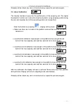
Page 16: ...vision Options 1 2 5 10 20 50 Cap Cap 1 To select first capacity Cap 2 To select second capacity Cal Calibration SECTION 7 CALIBRATION Select technical parameter CAL mode and select desired setting Linear linear calibration and nonLin Normal Calibration 7 1 Normal Calibration nonLin Enter the function by pressing display will be shown Make sure there are no loads on the platform and wait few secon...

Page 17: ...s weight should be1 4 of the max capacity and wait few seconds for to show display Load the second calibration mass weight on the platform mass weight should be2 4 of the max capacity and wait few seconds for to show display Load the third calibration mass weight on the platform mass weight should be3 4 of the max capacity and wait few seconds for to show display Load the fourth calibration mass w...

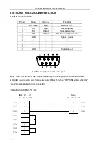
Page 18: ...power on 5 GND Signal ground 6 7 8 9 GND Signal ground Note Tare from outside of the scale is available by connecting the INPUT line and SIGNAL GROUND by a transistor switch or a relay contact Max 15V while OFF SINK 20mA while ON Tare Zero adjusting when it is connected connection with IBM PC AT 1 2 3 4 5 6 7 8 9 D SUB 9 pin male connector rear panel 5 3 2 3 2 5 1 7 8 6 4 TXD RXD GND DCO RTS CTS D...

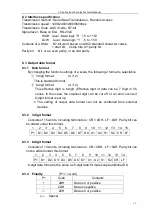
Page 19: ...f 2 This effective digit is 6 digit Effective digit of data can be 7 digit in VC series In this case the smallest digit can be cut off or an error occurs if 6 digit format is set up The setting of output data format can not be controlled from external devices 8 3 2 7 digit format Consists of 15 words including terminators CR 0DH LF 0AH Parity bit can be added under this format 1 2 3 4 5 6 7 8 9 10...

Page 20: ... Kilogram kg G gram g M G Milligram mg P C Quantity PCS 8 3 7 Judgment result Type of data S1 1 word S1 Code Contents Judgment results L 4CH Short LO Limit function is set and Quantity data output only G 47H Proper OK H 48H Exceed HI U 55H Unit weight Type of data T 54H Total weight p 70H Lower limit value q 71H Upper limit value 20H No judgment No set of type of data Pieces and weight 8 3 8 Statu...

Page 21: ...nsmits acknowledgment or the demanded data by transmission command If the command is erroneous or the received command is no effective the scale transmits non acceptance When the scale indicates quantity on the display properly the response is transmitted in 1 second after transmission of the command When the command is received in such operation of the scale as settings of unit weight judgment va...

Page 22: ...3 Code Contents A 0 0 41H 30H 30H Proper completion E 0 1 45H 30H 31H Command error Wrong command received other errors E 0 2 45H 30H 32H Value format error Too much digit No data etc E 1 0 45H 31H 30H The set unit weight value is error No memory of unit weight E 1 2 45H 31H 32H Limit function is not under operation 8 4 4 Tare Zero adjustment command Command Contents ParameterAddress Value Respons...

Page 23: ...th regard to a supplement and notice of each operation refer to 7 Function settings of a scale O8 O9 command means the data demand command to a scale Note2 When the set each condition works properly the data which is set in the function setting of a scale 41 da is transmitted Note3 After carrying out O0 to O9 command the condition is kept until next command is inputted However in the case that it ...

Page 24: ... A00 Proper completion E02 Value is not an integer 8 4 8 Limit function check Command Contents Parameter Response C1 C2 Command Address Value L 9 4CH 39H Quantity limit function is checked if it is worked properly Nil Nil A00 Proper completion E12 Limit function is not worked 8 4 9 Command sample T CR LF Tare O1 CR LF Setting constant output 1 O0 CR LF Stopping output O8 CR LF Outputting data 1 W1...

Page 25: ...nsportation or the time lapse Calibrate the scale Weighing pan is contacting the dust cover or the like Weighing objects are contacting with the wind shield Power voltage is not enough for the unit Weighing objects are non uniform Weighing objects included foreign matters or some irregular material Sampling operation is some fault Weighing mechanism is something wrong Wrong linearity Characteristi...

Page 26: ...ght When out of order l err When the piece weight is ligher than the countable piece weight piece weight less than capacity 60 000 10 2 Other Message message describe func At the time of the call of various functions and calibration function cal At the time of the start of the calibration by the external weight on 0 Under the zero point directions at the time of the calibration by external weight ...

Reviews: