5.
Secure the fork arm with the lifting device (e.g. using a crane and belts). Raise to a
height that allows for the fork carrier to be enclosed by both hooks.
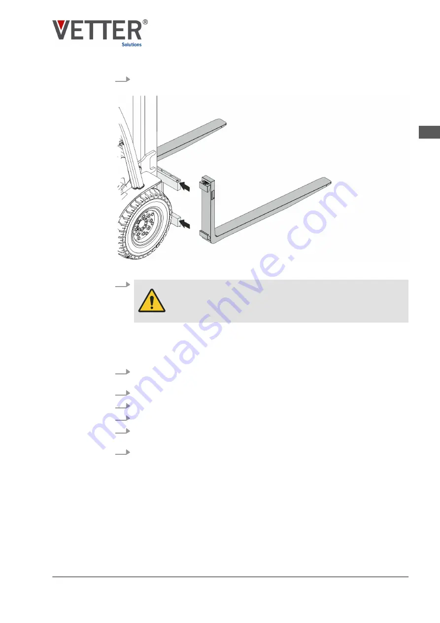
Fig. 7: Pushing the SmartFork
®
onto the fork carrier
6.
WARNING!
Risk of hands and other body parts being crushed when
aligning and pushing on!
Grip the Smart
Fork
®
at the head and fork blade with someone else to assist you
and carefully slide it onto the fork carrier from the outside using appropriate force
(Fig. 7). Ensure that the upper and lower hooks of the Smart
Fork
®
enclose the pro-
file of the fork carrier.
7.
Repeat the procedure for the second Smart
Fork
®
. Carry out assembly from the
other side of the fork carrier.
8.
Align both fork arms evenly to the centre of the fork carrier at the requisite width.
9.
Lock both fork arms by closing the lever inside the locking grooves.
10.
Fit the locking screw on the fork carrier again.
11.
Connect the Smart
Fork
®
to the shared equipotential bonding of the industrial truck
“Establishing equipotential bonding” on page 32
12.
Lower the fork carrier to the base position.
Assembly
Installing the SmartFork® on the fork carrier
EN
SmartFork
®
FrontCam ATEX for use in the Ex zone - BVS 20 ATEX E 108 X
31


