3.2
Suspension
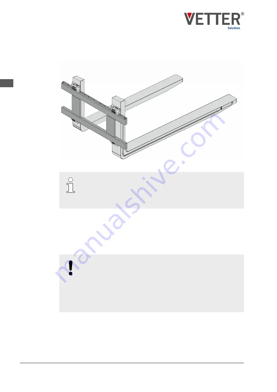
Fig. 5: SmartFork
®
on the fork carrier
The type of fork arm suspension may deviate from the image depending
on the industrial truck. In addition to the hook suspension shown, other
suspension options are available, e.g. shaft suspension. For information
about assembly of this variant, please refer to the operating instruction for
the industrial truck and for the fork carrier used.
Assembly of the Smart
Fork
®
may only be carried out on a fork carrier that is compatible
with the Smart
Fork
®
supplied. In this context, compatible means that both hooks jointly
and securely encompass the fork carrier and, due to the design of the fork carrier profile,
a secure lock can be ensured by the locking device on the upper hook. Observe the rele-
vant operating instruction for the fork carrier installed on the industrial truck.
The attachment dimensions for the Smart
Fork
®
can be requested from customer service
) upon stating the order number (on the hard stamping).
NOTICE!
Providing equipotential bonding
Potential differences can result in dielectric breakdown and discharge as
short, high electric current. In this regard, there is a danger of flammable
substances being ignited in potentially explosive atmospheres.
– Following assembly of the fork arms on the industrial truck, ensure a
connection (contact) to the shared equipotential bonding of the indus-
“Establishing equipotential bonding” on page 32
Structure
Suspension
SmartFork
®
FrontCam ATEX for use in the Ex zone - BVS 20 ATEX E 108 X
28
EN


