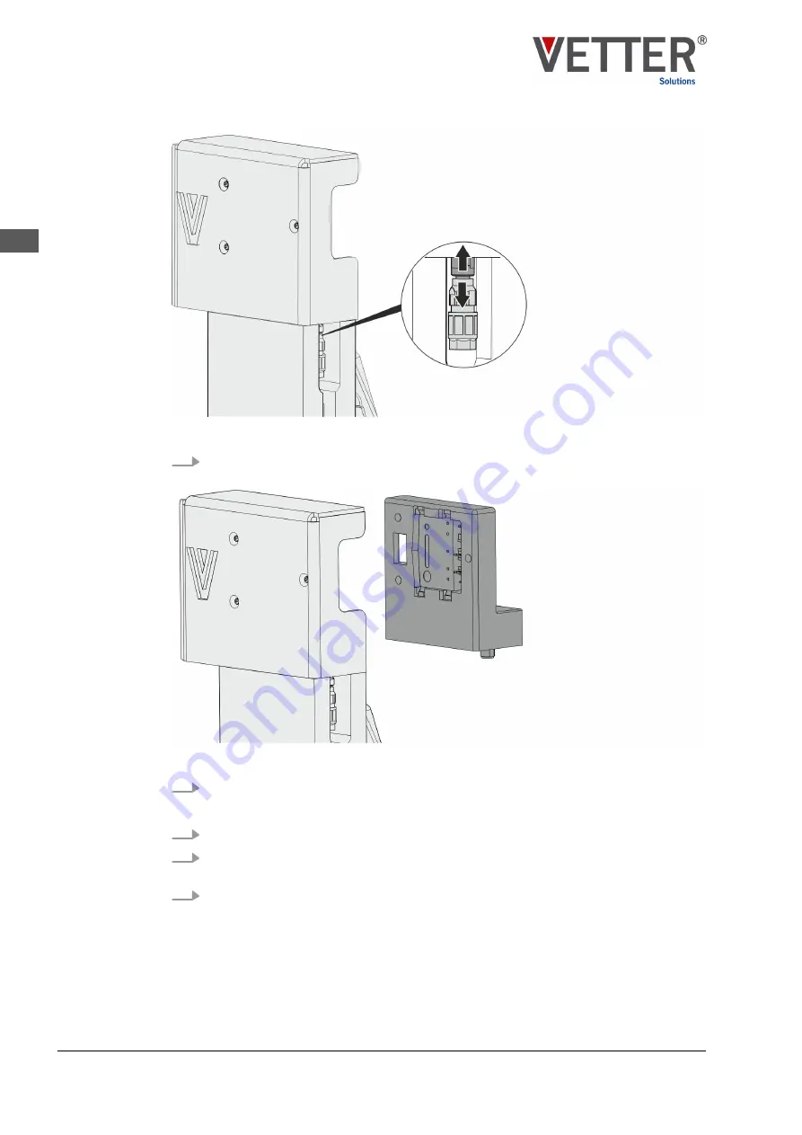
Fig. 9: Cable connections of the SmartSupply variant BAT
3.
Loosen the connection between the M8 socket housing and the plug of the cable
connection to the sensor system by unplugging the plug (Fig. 9).
Fig. 10: SmartSupply variant BAT
4.
Remove the Smart
Supply
at the open side of the connection panel (Fig. 10).
1.
Insert the Smart
Supply
into the connection panel on the fork head (Fig. 10).
2.
Insert the three countersunk screws into the outer surface of the connection panel
(Fig. 8) and screw them into housing of the Smart
Supply
.
3.
Establish the cable connection via a connection to the M8 connector (Fig. 9).
Assembly,
SmartSupply
Maintenance
Replacement of the SmartSupply
SmartFork
®
SmartSupply
22
EN
Summary of Contents for SmartFork SmartSupply SF-SUPPLY-V10-00X
Page 2: ...SmartFork SmartSupply 2 EN ...
Page 27: ......


