41
V.01/2021
SmartTarget
4.1 Installation
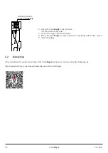
Video instructions for correct installation of the SmartTarget fork back can be found under the following link.
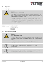
https://www.smartfork.com/en/support/operating-instructions-smarttarget
4.1.1 Adjusting the laser
The SmartTarget laser is adjusted in the optimum setting when the laser line marks the middle of the fork tip. It is advisable to
readjust the laser if the position of the laser line deviates.
1. Loosen the fastening screws on the laser module.
2.
You can now adjust the position of the laser module using the oblong holes.
3. The laser line should mark the middle of the fork tip.
4. Tighten the screws again.
5. Check that the laser line is in the correct position.
4.1.2 Shortening the SmartTarget when incompatible with the fork carrier
Depending on the type of fork carrier, under certain circumstances the height of the head plate may prevent installation of the
SmartTarget. In this case, the head plate can be removed and the SmartSupply fitted in the fork back. Proceed as follows:
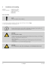
1. Remove battery (if inserted).
2. Loosen the plug-in connections of the SmartSupply.
3.
Remove
the
SmartSupply by loosening the screwed connection between
head
plate
and
the
SmartSupply.
4. Cut off the head plate at the intended point.
5. Apply the enclosed edge protection profile (piping tape) to the cut edge.
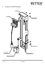
4 oblong holes for
adjusting the laser
module
Cut-off point for
head plate
Screwed connection
for the SmartSupply
and head plate
(3 screws)
WARNING!
Risk of injury
WARNING!
Risk of injury
Summary of Contents for SmartTarget ST-2A-GK-01
Page 24: ...24 SmartTarget V 01 2021 ...

