71
Q1
R1
61
91
92
93
95
L1
L2
L3
L4
L5
R3
R2
19/94
15
58
17/19
31
D1
D2
D3
D4
D5
D6
D7
D8
D9
D10
L6
BZ
G
3Y
B4
B1
B2
B5
B3
B6
p
ϑ
ϑ
Coolant
temp.
Exhaust
temp.
A1
A3
A4
A2
A5
A6
Alternator
D+
W
B+
Fuel valve
Fuel pump
Pre-heating
Starter motor
Oil
press.
30
85
87
86
30
85
87a
86
30
85
87
86
A1
A3
A4
A2
A5
A6
B4
B1
B2
B5
B3
B6
Red
Yellow
Orange
Violet
White
Black
ETR
W
Transparent
Yellow/
Green
Green Brown Blue Gray
Battery charging
J3
J4
Battery
Battery
main
switch
Fuse or
circuit breaker
Pre-
heating
relay
Auxiliary
start relay
Stop relay
Plug 'A'
Socket 'A'
Warning lights
Pre-
heating
M
M
Engine panel model
'10'
Key switch
Plug 'B'
Socket 'B'
Options, panel model ‘10’
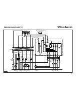
Wiring diagram
VD00240
Summary of Contents for VH4.65
Page 1: ...VH4 65 VH4 80 Operation manual...
Page 2: ...VD01079 VH4 80...
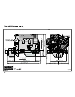
Page 74: ...72 Overall Dimensions 1 10 VH4 65 VD00235...
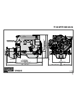
Page 75: ...73 Overall Dimensions VH4 80 1 10 VD00236...
Page 76: ...74...
Page 77: ...75...
Page 78: ...76...


