26
370301.01
vetus®
Installation instructions and operation manual E-Line electric propulsion
1
2
PCB
PCB
1
3
2
The image shown is for illustrative purposes and may differ from the
indicated product. For the exact data, consult the manual of the re-
spective control panel.
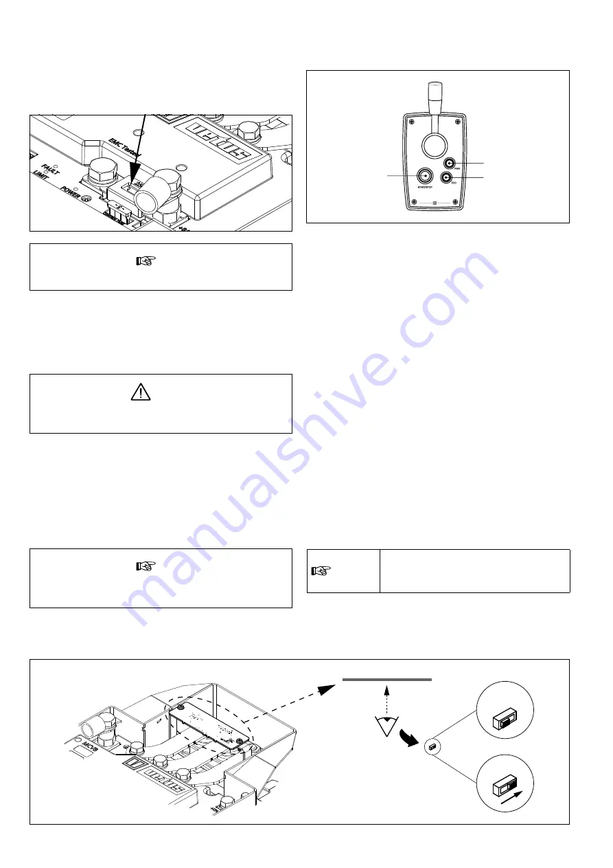
Start/Stop control button (1)
With this button the system can be switched on and off. In addition,
this button can be used to take over the command if multiple steer-
ing positions are used.
Power mode (if available) (2)
Pressing the POWER modus button unleashes the electric peak pow-
er of the E-Line motor. Press the button again to return to the NOR-
MAL mode.
The POWER mode will automatically switch off after a few minutes,
after which the mode will be temporarily unavailable.
Eco mode (if available) (3)
By pressing the ECO modus button the maximum output power of
the E-Line motor is limited. Press the button again to return to the
NORMAL mode.
7 .9 Connecting CAN bus (control current) cables
See diagrams from page
if multiple panels have to be connect-
ed.
n
ote
The CAN bus power supply must always be
connected to 12 Volt . Use the V-CAN key
switch (e .g . MPE1KB) as power supply .
7 .8 The motor control panel
n
ote
Always replace a defect fuse by a fuse of the same value .
7 .7 Configuration of one or more motors
By default, the E-Line motor is configured for use in a single-motor
propulsion system. Only if multiple motors are installed one of the
E-Line motors must be configured.
D
anGer
Only work on the system when the motor is stopped and the
electrical system is switched off .
• Remove the cover and flip the switch. It is located on the under-
side of the circuit board (PCB). If necessary, temporarily loosen the
bolts and nuts on the PCB holder.
• Move the switch from position 1 to position 2. The E-Line motor is
now configured for use in a multi-motor system.
• Replace the cover.
n
ote
The direction of rotation of the motor can be set on the
control panel .
7 .6 Internal fuse
There is an internal fuse on the controller in the connection box.
This fuse protects the controller and the motor against short circuits
or overload.
Summary of Contents for ELINE050
Page 2: ...2 370301 01 vetus Installation instructions and operation manual E Line electric propulsion ...
Page 4: ...4 370301 01 vetus Installation instructions and operation manual E Line electric propulsion ...
Page 43: ...370301 01 43 vetus Installation instructions and operation manual E Line electric propulsion ...


