50
400202.01
vetus®
Installation manual VF4 VF5
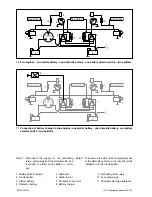
5.3.8 Mechanical installation
C
O
M
M
A
N
D
E
N
G
IN
E
2
W
A
R
M
/S
E
N
G
IN
E
1
132 (5
3
/
16
”)
43
(1
11
/
16
”)
4 x M5
35
(1
3
/
8
”)
20
(
13
/
16
”)
114 (4
1
/
2
”)
174 (6
7
/
8
”)
155 (6
1
/
8
”)
155 (6
1
/
8
”)
130 (5
1
/
8
”)
32
(1
1
/
4
”)
35
(1
3
/
8
”)
300 (11
13
/
16
”)
350 (13
3
/
4
”)
280 (11”)
332 (13
1
/
16
”)
210
(8
1
/
4
”)
25 (1”)
ø 20
(
3
/
4
”)
Flexible mounts
Connections
Install the control box at least 25 cm (10 in) from the wall.
Do not install the control box with
the plugs upwards.
Dimensions of the
command station
Dimensions of the
control box
Installation of the control box
Summary of Contents for VF4.140E
Page 1: ...Installation manual VF4 VF5 VF4 140E VF4 170E VF4 190E VF5 220E VF5 250E ...
Page 2: ...vetus Installation manual VF4 VF5 400202 01 Copyright 2012 Vetus n v Schiedam Holland ...
Page 22: ...20 400202 01 vetus Installation manual VF4 VF5 ...
Page 68: ...66 400202 01 vetus Installation manual VF4 VF5 ...
Page 71: ...400202 01 69 vetus Installation manual VF4 VF5 ...
Page 72: ...340401 01 12 07 Nederlands Printed in the Netherlands Vetus Diesel VF4 VF5 Nederlands ...


