4.6
Signal Input Circuit
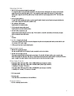
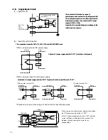
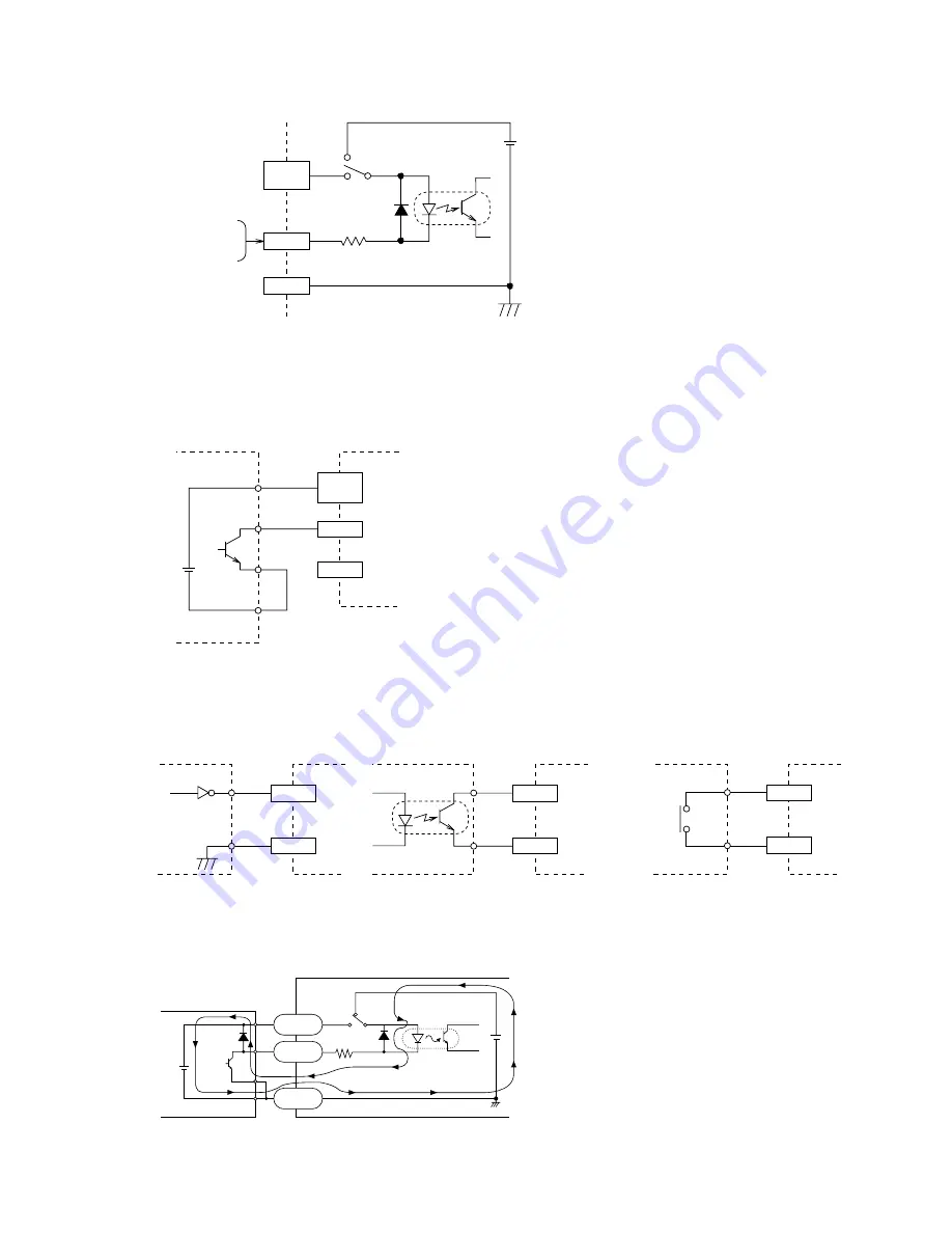
(1) Input Circuit
The input circuits function by means of
photocoupler input, as shown in the diagram at left.
The input photocoupler can be driven by either the
internal power supply or by an external DC power
supply (DC24V ±10%).
Input circuit is insurated dangerous voltages by the
reinforce photo couplers.
(2) Input Circuit Connection
This connection is used for EXT.VR. , CW, CCW, and SLOW DOWN input
■
When using an external DC power supply
Flip the I/O power supply switch to "EXT." (set at time of shipment).
■
When using the driver's built-in power supply
Switch the I/O power supply switch to "INT." Signals will not be input if it is set to "EXT.".
■
Cautions to observe when using a controller with an internal clamp diode
When using a controller with an internal clamp diode,
the
Ⅰ
/ O
power supply switch to " EXT." .
If the
Ⅰ
/ O
power supply swith is the " INT." position,
current will flow as indicated by the arrows in the
diagram, thereby causing the motor to run
unexpectedly.
14
4.8k
Ω
EXT.
Reinforce photo coupler
INT.
/ O power supply swich
(front panel)
EXT. VR
CW
CCW
SLOW DOWN
INPUT
COM
Input
GND
GND
Transistor
Cotroller
Driver
GND
+24V
Input
INPUT
COM
Photocoupler
Input
TTL7406 or
equivalent
Controller
《
Non-contact control
》
Driver
Controller
Driver
Controller
Driver
GND
Input
GND
Input
Relay
《
Contact control
》
GND
Driver
INPUT
COM
INT.
EXT.
GND
Input
560
Ω
TLP521 or equivalent
Controller
Clamp
diode
Transistor
+24V

