5.3
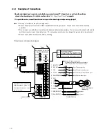
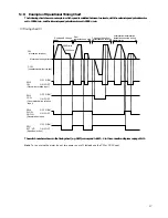
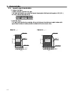
Example of Operational Timing Chart
The following chart shows an example in which speed is switched between two levels, with the external speed potentiometer
set to 1000 r/min, and the internal speed potentiometer set to 3000 r/min.
[
Timing chart
]
The switch numbers shown in the timing chart (e.g. SW2) correspond to SW1−4 in the connection diagram on page 10-11.
Note To run or stop the motor, do not turn power on or off. Instead use the CW or CCW input.
Run/speed change
/stop
3000r/min
1000r/min
Run/
Instantaneous stop
Change of direction/
instantaneous reverse
Acceleration/deceleration
instantaneous stop during
deceleration
CW
(clockwise rotation)
CCW
(counter
clockwise rotation
)
OFF “HIGH”
ON “LOW”
Motor operation pattern
(Clockwise rotation input)
SW2
CW
(Counterclockwise rotation
input)
SW3
CCW
(Deceleration input)
SW4
SLOW
DOWN
(Speed selection)
SW1
EXT. VR
OFF “HIGH”
ON “LOW”
OFF “HIGH”
ON “LOW”
OFF “HIGH”
ON “LOW”
17

