background image

AUTOMIX 10 (EN) 0508 

80

70

60

50

40

30

20

C

90

o

5

-10

+10 0

2

-20 -30

C

o

1

3

4

6

8

7

9

-40 -50

GRAPH SETTING 


The regulating graph for a certain house is dependent on dimensions, location, insulation etc. Therefore it is 

not possible to decide on a graph in advance. It has to be tried out. 

The graph is set with knobs D and F. The knobs work steplessly. 


Initial setting 
Regulating graph for radiator heating, set knob D on 5. 

Regulating graph for floor heating, set knob D on 2. 


Room temperature setting/parallel displacement 
For parallel displacement / to obtain the desired room temperature use knob F. The supply water 

temperature can be raised or lowered steplessly by 10°C from setting 0. A supply water temperature  of 

2,5ºC corresponds to 1ºC  in room temperature. 


Adjustments 
Should the room temperature rise with falling outdoor temperature:  lower knob 


raise knob F 


Should the room temperature fall with falling outdoor temperature:  raise knob D 


lower knob F 


Make only minor changes with knobs D and F. When the house has an even room temperature despite 

fluctuating outdoor temperatures, the correct regulating graph has been obtained. 


N.B! Heat affects slowly. When a temperature setting has been changed it takes several hours before the 

room temperature corresponds to the new setting due to dimensions of the heating system and the insulation 

of the house. A floor heating system responds even slower to a new setting than a radiator system. 


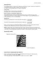
REGULATING GRAPHS 


Supply water temperature 


Outdoor temperature 


RIGHT OR LEFT TURNING DIRECTION OF MOTOR 


Right or Left turning direction of the motor is selected with knob E. At delivery the motor opens the 

mixing valve clockwise. Knob is at R = RIGHT. 

If the mixing valve opens counter clockwise the knob is to be movde to L = LEFT.  


Summary of Contents for AUTOMIX 10

Page 1: ...UTOMIX 10 RB the room temperature can be set between 12 C and 27 C 6 Remote control AUTOMIX 10RC with 15 m wire art no 1212 Remote control AUTOMIX 10RC is designed for floor heating systems The remote control provides a convenient way to adjust the supply water temperature without going to the boiler room MOUNTING Supply water sensor T1 Supply water sensor T1 is fastened to a non insulated part of...

Page 2: ...ckwise position Turn scale E according to the open closed direction of the valve 5 Place handle F onto the motor ensuring that the arrow points to the left end position of the scale Tighten the whole unit by means of screw G 6 Using a screwdriver No 3 turn the disengaging button H from A to HAND position and rotate the valve with handle F from one end position to the other It is important that the...

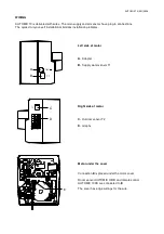
Page 3: ...have plug in connections The quick do it your self installation minimizes installation problems Left side of motor A Adapter B Supply water sensor T1 Right side of motor C Outdoor sensor T2 D Graphs Motor under the cover Connection E is placed under the motor cover Room sensor AUTOMIX 10RB and remote control AUTOMIX 10RC are connected to E The cover has edge cuttings for the wire ...

Page 4: ...temperature rise with falling outdoor temperature lower knob D raise knob F Should the room temperature fall with falling outdoor temperature raise knob D lower knob F Make only minor changes with knobs D and F When the house has an even room temperature despite fluctuating outdoor temperatures the correct regulating graph has been obtained N B Heat affects slowly When a temperature setting has be...

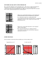
Page 5: ...y water temperature is selected with knob C In the example graph 3 has been selected and the min supply water temperature is set to 22 C Max supply water temperature will automatically be 40 C Setting of max supply water temperature is used in hydronic radiator heating systems Max supply water temperature is selected with knob C In the example graph 6 has been selected Max supply water temperature...

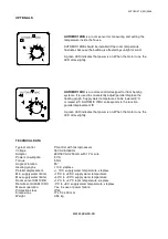
Page 6: ...parallel displacement F A green LED indicates that power is on When the motor runs the LED dims slightly TECHNICAL DATA Type of control PI control with microprocessor Voltage 18 VAC 50 60 Hz Adapter 230 18 VAC 200 mA with 1 7 m wire Power consumption 3 VA Torque 5 Nm Angle of rotation 90 Heating graphs 1 to 9 stepless Parallel displacement 10 C supply water temperature stepless Min supply water li...

Reviews: