background image

WARM-UP SEQUENCE 

As with all tube amplifiers, gradual warm-up greatly extends tube life and tone quality. There are 
two major wear factors which can noticeably impact the performance of preamp tubes. The first is 

Filament Stress

. The second is called 

Cathode Stripping


Filament Stress

 occurs when a cold tube is allowed to heat up too quickly. If this stress is 

allowed to occur too often, it is possible to destroy the filament, in which case the tube will cease 
to function. This is not a big problem in vintage amplifiers with AC powered heaters, which 
normally exhibit an inherently slow warm-up characteristic. However, AC filament generated 
hum can become intolerably loud in amplifiers with very high-gain capability. A regulated DC 
filament supply like that used in the GP3 totally eliminates the hum. As low maintenance is a top 
priority in the GP3, great care has been taken in the design of the filament supply in order to 
prevent Filament Stress. To insure low noise and long tube life, the 

Regulated DC Filament 

Supply

 in the GP3 has a 

“Ramp”

 feature, which upon power-up slowly raises the heater voltage 

up to the optimum voltage required by the tubes. 
 

Cathode Stripping

 occurs when high voltage is supplied to the tube before the tube filament or 

heater is adequately warmed up and fully stabilized. Cathode Stripping eventually causes the tube 
to lose gain prematurely, resulting in dull tone and loss of sustain. To prevent Cathode Stripping, 
we’ve incorporated another exclusive feature into the GP3, the 

High Voltage Auto-Standby 

Timer

.  

 
During power-up, the channels automatically MUTE and the three channel LED indicators begin 
to flash, indicating that the warm-up sequence has begun. After 15 seconds, the time it takes for 
the tube filaments to reach operating temperature, a timer function in the GP3s microprocessor 
sends a “Turn On” command to the high voltage supply and the Clean channel LED turns on. 

Note: If you have previously powered down your GP3 in a different channel, that channel 
and its global settings will activate after the warm-up sequence is complete

. Once the high 

voltage supply has been activated and stabilized, the output mute relay deactivates and the GP3 is 
ready to play. The entire 

Warm-Up Sequence 

takes 18 seconds to complete.  

 
Of course, there may be times when it is not convenient to wait 18 seconds for the GP3 to begin 
operating. If you are mid-solo at a gig or recording session for example and there is a momentary 
interruption in AC power, the GP3 may still be warm enough to begin operating immediately. In 
this case, simply press the global CHANNEL key right after power has been restored to the GP3. 
This will initiate a modified 3-second turn-on sequence, which will then automatically return you 
to your previous settings. 


THE BIG PICTURE 

The Valvulator™ GP3 is a complete, self-contained 

Very Low Power

 amplifier. Utilizing its 

groundbreaking 

Dynamic Sensing Technology™

 incorporating a unique output power circuit; 

the GP3 reacts to playing dynamics the same way a conventional guitar amplifier does. With user 
control over this dynamic “expression”, you can dial in the ideal dynamic response of the GP3 to 
suit your style.  
 
A typical tube guitar amplifier is made up of a preamp stage, which consists of preamp tubes, 
gain stages and a tone control system, and a power amp stage, which consists of power tubes and 
an output transformer. A great guitar amplifier is born when the preamp and power amp 
complement and interact with each other such that the whole becomes greater than the sum of its 

Summary of Contents for Valvulator GP3

Page 1: ...VALVULATOR GP3 VERY LOW POWER VACUUM TUBE GUITAR AMPLIFIER PRELIMINARY OWNERS MANUAL...

Page 2: ...ce of musical equipment I sincerely apologize in advance for the depth of detail you are about to encounter Having devoted countless hours culminating in decades to the creation of the GP3 I would not...

Page 3: ...D ABOUT CLASSIC AMPLIFIER SOUNDS 5 THE BIG PICTURE 6 INPUT STAGE 7 CHANNELS 8 TONE CONTROLS 9 GRAPHIC EQUALIZER 10 DYNAMICS CONTROL 11 OUTPUT STAGE MASTER VOLUME 12 GLOBAL FUNCTIONS 13 MIDI MIDI LEARN...

Page 4: ...ble from the rear panel of your GP3 to any convenient wall outlet or power strip Connect one end of a shielded guitar cable to the AMP OUT jack on the rear panel of your GP3 Plug the other end of this...

Page 5: ...t here for the purpose of demonstrating how adept the GP3 would be at recreating classic amplifier sounds We feel that this is an unproductive exercise often based on sleight of hand and the power of...

Page 6: ...arm up sequence has begun After 15 seconds the time it takes for the tube filaments to reach operating temperature a timer function in the GP3s microprocessor sends a Turn On command to the high volta...

Page 7: ...ween the guitar and the various amp and effect inputs to condition and protect the guitar signal from noise and tonal degradation These buffers are often makeshift items and are almost always detrimen...

Page 8: ...AD feature Gain Treble Middle Bass and Volume controls The LEAD and RHYTHM channels also feature a variable BOOST control to adjust the amount of gain boost available A fixed amount of boost is provid...

Page 9: ...erdrive used audience size relationship with the bartender and a host of other variables In the process the amplifier produces varying degrees of distortion harmonics overload and power amp compressio...

Page 10: ...MASTER VOLUME and DYNAMICS you will become very proficient at fine tuning the output stage to emulate the output behavior of say a 100 watt amp versus a 15 watt amp GLOBAL FUNCTIONS On the far right o...

Page 11: ...AD channel Simultaneously mutes all three channels when held down for 2 seconds WARM UP SEQUENCE OVERRIDE This function is accessed right after power up In the event that the GP3 has already been oper...

Page 12: ...create NOTE Your existing program parameters remain unaffected until you change them even if you enter MIDI LEARN mode live on the fly This means that if you are playing a live performance and you de...

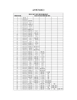
Page 13: ...T 21 CLEAN BRITE FAT LOOP 22 CLEAN BRITE FAT EQ 23 CLEAN BRITE BOOST LOOP 24 CLEAN BRITE BOOST EQ 25 CLEAN BRITE LOOP EQ 26 CLEAN FAT BOOST LOOP 27 CLEAN FAT BOOST EQ 28 CLEAN FAT LOOP EQ 29 CLEAN BOO...

Page 14: ...5 RHYTHM BRITE BOOST LOOP 66 RHYTHM BRITE BOOST EQ 67 RHYTHM BRITE LOOP EQ 68 RHYTHM FAT BOOST LOOP 69 RHYTHM FAT BOOST EQ 70 RHYTHM FAT LOOP EQ 71 RHYTHM BOOST LOOP EQ 72 RHYTHM BOOST LOOP REMOTE 73...

Page 15: ...08 LEAD BRITE BOOST EQ 109 LEAD BRITE LOOP EQ 110 LEAD FAT BOOST LOOP 111 LEAD FAT BOOST EQ 112 LEAD FAT LOOP EQ 113 LEAD BOOST LOOP EQ 114 LEAD BOOST LOOP REMOTE 115 LEAD BOOST EQ REMOTE 116 LEAD BRI...

Page 16: ...are listed under each location Numbering sequence is LEFT to RIGHT looking at the FRONT of the unit V1 Valvulator unity gain buffer stage effects loop driver 12AX7WB Sovtek V2 Input Gain Stage 1 and s...

Page 17: ...dently isolated from system ground REMOTE 2 Relay controlled switching jack for remote control of external amps preamps and effects Assignable to RHYTHM or LEAD channel function and can be configured...

Page 18: ...s including but not limited to cabinets cabinet parts or knobs 3 This warranty does not apply to uncrating setup installation or the removal and reinstallation of products for repair 4 This warranty s...

Reviews: