background image

AMOS

AMOS

AMOS

AMOS----820 User Manual

820 User Manual

820 User Manual

820 User Manual    

13 

3.

3.

3.

3.


Hardware Installation

Hardware Installation

Hardware Installation

Hardware Installation    

This chapter provides information about hardware installation procedures. It is recommended to use a 
grounded wrist strap before handling computer components. Electrostatic discharge (ESD) can damage 
some components. 

3.1.


Installing the Micro SD Card 

 
Step 1

Step 1

Step 1

Step 1    

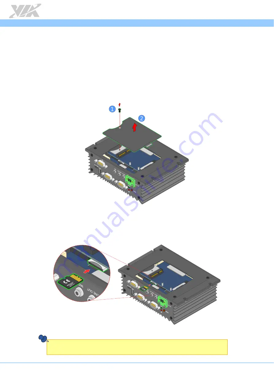
Locate the bottom access cover of the chassis. Loosen the screw to remove the bottom access cover. 


Figure 

Figure 

Figure 

Figure 19

19

19

19: 

:     Removing the bottom access cover

Removing the bottom access cover

Removing the bottom access cover

Removing the bottom access cover    

 
Step 

Step 

Step 

Step 2

2

2

2    

Gently slide the Micro SD card into the card slot reader with the label side facing down then press the 
card until it locks into place. 


Figure 

Figure 

Figure 

Figure 20

20

20

20: 

:     Inserting the Micro SD card

Inserting the Micro SD card

Inserting the Micro SD card

Inserting the Micro SD card    


Note:

Note:

Note:

Note:    

To remove the Micro SD card, press the card to disengage from the slot reader then gently pull out the card. 

Summary of Contents for AMOS-820 SKU

Page 1: ...1 08 07132016 170200 USER MANUAL AMOS 820 Fanless ultra compact quad core ARM system ruggedized for extreme environments ...

Page 2: ...ibed in this manual at any time without prior notice Regulatory Compliance Regulatory Compliance Regulatory Compliance Regulatory Compliance FCC FCC FCC FCC A Radio Frequency Interference Statement A Radio Frequency Interference Statement A Radio Frequency Interference Statement A Radio Frequency Interference Statement This equipment has been tested and found to comply with the limits for a class ...

Page 3: ...uch a way that people cannot step on it Always unplug the power cord before inserting any add on card or module If any of the following situations arises get the equipment checked by authorized service personnel The power cord or plug is damaged Liquid has penetrated into the equipment The equipment has been exposed to moisture The equipment has not worked well or you cannot get it work according ...

Page 4: ...bit Ethernet miniPCIe slot RCA in 12V DC in AMOS AMOS AMOS AMOS 820 820 820 820 2Q10A1 2Q10A1 2Q10A1 2Q10A1 Fanless embedded system with 1 0GHz NXP i MX 6Quad Cortex A9 SoC 1GB DDR3 RAM 4GB eMMC 512KB SPI Flash ROM HDMI 3 x USB 2 0 Micro USB 2 0 OTG 2 x CAN bus 2 x COM GPIO Gigabit Ethernet miniPCIe slot RCA in PoE function 12V DC in Optional Accessories Wireless Accessories Wireless Accessories W...

Page 5: ...l I O Pin Descriptions and Functionality External I O Pin Descriptions and Functionality External I O Pin Descriptions and Functionality 7 7 7 7 2 1 DC In Jack 7 2 2 Reset Button 7 2 3 LED Indicator 7 2 4 CAN COM2 Port 8 2 5 COM1 Port 8 2 6 USB 2 0 Port 9 2 7 Micro USB 2 0 Port 9 2 8 Audio Jacks 10 2 9 DIO Port 10 2 10 Micro SD SPI Boot Select Switch 11 2 11 Gigabit Ethernet Port LAN 11 2 12 HDMI ...

Page 6: ...tacle diagram 10 Figure 14 DIO port diagram 10 Figure 15 Micro SD SPI boot select switch diagram 11 Figure 16 Gigabit Ethernet port diagram 11 Figure 17 HDMI port diagram 12 Figure 18 RCA jack diagram 12 Figure 19 Removing the bottom access cover 13 Figure 20 Inserting the Micro SD card 13 Figure 21 Installing 3G Wi Fi module 14 Figure 22 Securing 3G Wi Fi module 14 Figure 23 Removing front back a...

Page 7: ...e 2 CAN COM2 port pinout 8 Table 3 COM1 port pinout 8 Table 4 USB 2 0 port pinout 9 Table 5 Micro USB 2 0 port pinout 9 Table 6 Audio jack receptacle pinout 10 Table 7 DIO port pinout 10 Table 8 Gigabit Ethernet port pinout 11 Table 9 Gigabit Ethernet port LED color definition 11 Table 10 HDMI port pinout 12 Table 11 RCA jack pinout 12 ...

Page 8: ... Ethernet port two USB 2 0 ports one HDMI port and one composite RCA jack 1 1 Key Features 1 1 1 ARM based System With an NXP i MX 6Quad Cortex A9 ARM SoC the VIA ARM based system AMOS 820 delivers powerful performance to a host of connected device applications 1 1 2 Fanless Ruggedized Ultra compact and Space saving The AMOS 820 has an ultra compact ruggedized chassis which is designed to save spa...

Page 9: ...ications The power over Ethernet PoE PD board can output 25W of power The AMOS 820 can be operated using either PoE or external adaptors 12V 1 1 10 Multiple Mounting Option The AMOS 820 supports multiple methods for mounting the chassis securely The rugged industrial PC can be mounted to a table wall or any flat surface 1 1 11 Embedded OS ready The AMOS 820 is 100 compatible with Android 4 4 2 and...

Page 10: ... USB USB USB USB o SMSC USB 2 0 high speed 4 port hub controllers CAN CAN CAN CAN o TI SN65HVD1050 EMC optimized CAN transceiver Expansion I O Expansion I O Expansion I O Expansion I O o 1 x MiniPCIe slot o Optional support Ublox ZU200 3 75G UMTS HSPA 3G module or VNT9485 IEEE 802 11 b g n Wi Fi module Front Front Front Front Panel I O Panel I O Panel I O Panel I O o 1 x Reset button o 1 x Power L...

Page 11: ...o Operating Operating Operating Operating Humidity Humidity Humidity Humidity 0 90 45 C non condensing o Vibration Loading During Operation Vibration Loading During Operation Vibration Loading During Operation Vibration Loading During Operation with onboard eMMC with onboard eMMC with onboard eMMC with onboard eMMC 7Grms IEC 60068 2 64 random 5 500Hz 1hr axis o Shock During Operation Shock During ...

Page 12: ... Manual 5 1 3 Panel Layout Figure Figure Figure Figure 1 1 1 1 Front panel I O layout Front panel I O layout Front panel I O layout Front panel I O layout Figure Figure Figure Figure 2 2 2 2 Back panel I O layout Back panel I O layout Back panel I O layout Back panel I O layout ...

Page 13: ...dimension Front side view dimension Front side view dimension Front side view dimension Figure Figure Figure Figure 4 4 4 4 Top Top Top Top side view side view side view side view dimension dimension dimension dimension Figure Figure Figure Figure 5 5 5 5 Back side view dimension Back side view dimension Back side view dimension Back side view dimension ...

Page 14: ... DC DC in jack in jack in jack in jack diagram diagram diagram diagram Pin Pin Pin Pin Signal Signal Signal Signal 1 12V DC 2 GND Table Table Table Table 1 1 1 1 DC DC DC DC in jack in jack in jack in jack pinout pinout pinout pinout 2 2 Reset Button The AMOS 820 comes with a reset button on the front panel Figure Figure Figure Figure 7 7 7 7 Reset button diagram Reset button diagram Reset button ...

Page 15: ...NL1 7 GND 8 CANH2 9 VCC5 Table Table Table Table 2 2 2 2 CAN COM2 CAN COM2 CAN COM2 CAN COM2 port port port port pinout pinout pinout pinout Note Note Note Note Do not directly plug a COM port to the CAN COM2 port Please use the COM CAN conversion cable when connecting to the CAN COM2 port 2 5 COM1 Port The integrated 9 pin COM port uses a male DE 9 connector The COM1 port supports the RS 232 stan...

Page 16: ...D Table Table Table Table 4 4 4 4 USB USB USB USB 2 2 2 2 0 port pinout 0 port pinout 0 port pinout 0 port pinout 2 7 Micro USB 2 0 Port The AMOS 820 comes with a Micro USB 2 0 type B port located on the front panel The Micro USB 2 0 type B port supports OTG and it offers expandable storage Figure Figure Figure Figure 12 12 12 12 Micro Micro Micro Micro USB USB USB USB 2 0 2 0 2 0 2 0 port diagram...

Page 17: ...ng Line Line Line Line i i i in n n n Line Line Line Line o o o out ut ut ut Mic Mic Mic Mic i i i in n n n Tip Left channel in Left channel Left channel Ring Right channel in Right channel Right channel Sleeve Ground Ground Ground Table Table Table Table 6 6 6 6 Audio jack receptacle pinout Audio jack receptacle pinout Audio jack receptacle pinout Audio jack receptacle pinout 2 9 DIO Port The 9 p...

Page 18: ...gnal pair 2 4 Signal pair 3 5 Signal pair 3 6 Signal pair 2 7 Signal pair 4 8 Signal pair 4 Table Table Table Table 8 8 8 8 Gigabit Ethernet port pinout Gigabit Ethernet port pinout Gigabit Ethernet port pinout Gigabit Ethernet port pinout The Gigabit Ethernet port RJ 45 port has two individual LED indicators located on the front side to show its Active Link status and Speed status Link LED Link L...

Page 19: ...l Signal Signal Signal 1 TMDS Data0 2 GND 3 TMDS Data0 4 TMDS Data1 5 GND 6 TMDS Data1 7 TMDS Data2 8 GND 9 TMDS Data2 10 TMDS Data3 11 GND 12 TMDS Data3 13 CEC 14 NC 15 HDMI Clock 16 HDMI Data 17 GND 18 HDMI Power 19 Hot Plug Detect Table Table Table Table 10 10 10 10 HDMI HDMI HDMI HDMI port pinout port pinout port pinout port pinout 2 13 RCA Jack The AMOS 820 is equipped with a RCA jack labeled...

Page 20: ...over of the chassis Loosen the screw to remove the bottom access cover Figure Figure Figure Figure 19 19 19 19 Removing the bottom access cover Removing the bottom access cover Removing the bottom access cover Removing the bottom access cover Step Step Step Step 2 2 2 2 Gently slide the Micro SD card into the card slot reader with the label side facing down then press the card until it locks into ...

Page 21: ...Figure Figure Figure Figure 21 21 21 21 Installing 3G W Installing 3G W Installing 3G W Installing 3G Wi i i i Fi Fi Fi Fi module module module module Step 2 Step 2 Step 2 Step 2 Once the module has been fully inserted push down the module until the screw holes align with the standoff holes Then secure the module with screws Figure Figure Figure Figure 22 22 22 22 Securing 3G W Securing 3G W Secur...

Page 22: ...k back back back and bottom plate screws and bottom plate screws and bottom plate screws and bottom plate screws Step 4 Step 4 Step 4 Step 4 Carefully pull the back panel plate and the top cover chassis Then remove the antenna hole cover Figure Figure Figure Figure 24 24 24 24 Pulling out Pulling out Pulling out Pulling out back back back back panel panel panel panel plate and antenna hole cover p...

Page 23: ...ule Figure Figure Figure Figure 25 25 25 25 Installing 3G and W Installing 3G and W Installing 3G and W Installing 3G and Wi i i i Fi Fi Fi Fi antenna antenna antenna antenna Step 6 Step 6 Step 6 Step 6 Reinstall the top cover chassis and back panel plate then secure it with screws Step Step Step Step 7 7 7 7 Gently connect the other end of the 3G Wi Fi antenna cables to the micro RF connectors on...

Page 24: ...Manual 820 User Manual 17 Step 8 Step 8 Step 8 Step 8 Reinstall the bottom access cover Figur Figur Figur Figure e e e 27 27 27 27 Reinstalling bottom access cover Reinstalling bottom access cover Reinstalling bottom access cover Reinstalling bottom access cover ...

Page 25: ...Step 1 Step 1 Locate the area to install the rubber feet Step 2 Step 2 Step 2 Step 2 Attach carefully each rubber foot Firmly press it down to ensure the rubber foot is properly in place Figure Figure Figure Figure 28 28 28 28 Installing the rubber feet Installing the rubber feet Installing the rubber feet Installing the rubber feet ...

Page 26: ...20 system The rubber feet are not required when mounting the system on walls or tables 2 Do not use other types of screws on mounting the AMOS 820 system aside from the provided screws to avoid any damages Step 1 Step 1 Step 1 Step 1 Find a suitable surface to mount the AMOS 820 system Drill four holes on wall or table Ensure that holes diameter and the distance between holes perfectly match with ...

Page 27: ... Linux Sound Architecture project for integrated audio 4 2 Technical Supports and Assistance For utilities downloads latest documentation and new information about the AMOS 820 go to http www viatech com en systems industrial http www viatech com en systems industrial http www viatech com en systems industrial http www viatech com en systems industrial fanless fanless fanless fanless pcs amos pcs ...

Page 28: ......

Reviews: