12
L
AYOUT OF
I/O
C
OASTLINE
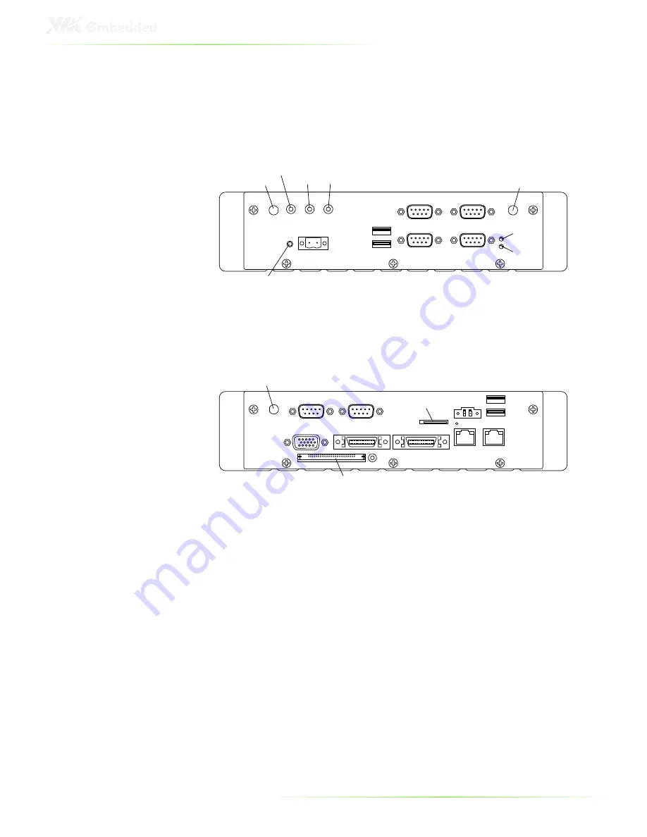
Front Panel Layout
Front I/O
3G antenna hole
WLAN antenna hole
Speaker-out
Line-in
MIC-in
Power button
DC-in
USB2
USB1
COM2
COM4
COM1
COM3
HDD LED
Power LED
Rear Panel Layout
Rear I/O
GPS antenna hole
UART
GPIO
VGA
LVDS1
LVDS2
Compact Flash slot
SIM card slot
LAN2
LAN1
DC-out
USB3
USB4
Summary of Contents for ART-5450
Page 12: ...XII ...
Page 13: ...1 1 Product Overview ...
Page 21: ...9 ART 5450 DIMENSIONS ...
Page 49: ...37 Step 2 Fasten the mounting brackets to the bottom side of the ART 5450 chassis as shown ...
Page 50: ...38 Step 3 Secure both mounting brackets to the wall table with four screws ...
Page 52: ...40 Step 4 Connect the power module to the power source using the provided cable ...
Page 54: ...42 Power Input Connector Pin Signal 1 IGN2 2 GND 3 DC 10 30V 4 ACC 5 GND 6 DC 10 30V 1 3 4 6 ...
Page 61: ...49 5 BIOS Setup This chapter gives a detailed explanation of the BIOS setup functions ...
Page 71: ...59 Summary Screen Show Show summary screen Settings Disabled Enabled ...
Page 100: ......
Page 101: ...89 6 Driver Installation ...


