21
G
IGABIT
E
THERNET
P
ORTS
1
AND
2
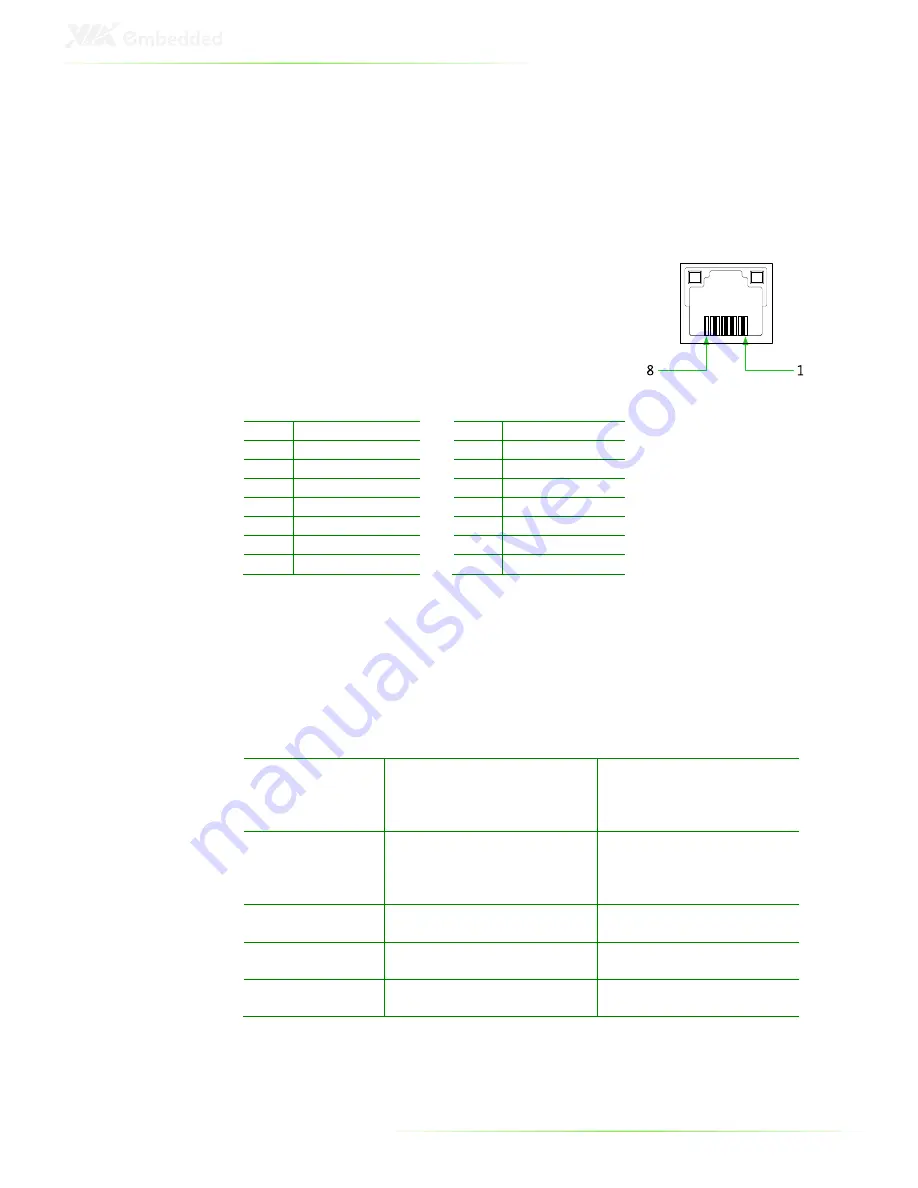
The ART-5450 system is equipped with two VIA VT6130 PCIe
Gigabit Ethernet controllers on the mainboard. The controllers
provide support for two Gigabit Ethernet RJ-45 ports (LAN1 and
LAN2) on rear I/O panel.
Both ports are fully compliant with IEEE
802.3 (10BASE-T), 802.3u (100BASE-TX), and
802.3ab (1000BASE-T) standards. The pin
assignments of LAN1 and LAN2 ports are
shown below.
LAN1
LAN2
Pin Signal
Pin Signal
1
L
1
L
2
LAN1_TD0-
2
LAN2_TD0-
3
L
3
L
4
LAN1_TD1-
4
LAN2_TD1-
5
L
5
L
6
LAN1_TD2-
6
LAN2_TD3-
7
L
7
L
8
LAN1_TD3-
8
LAN2_TD3-
Both LAN1 and LAN2 are equipped with two LED indicators
located to show its active/link status and speed status.
LAN LED Status
Link LED
(Left LED on RJ-45 port)
Active LED
(Right LED on RJ-45 port)
Active
The LED always On in
different color, and it
depends on different of LAN
connection speed
Flash in Orange color
Link
The LED always On in
different color, and it
depends on different of LAN
connection speed
LED is off
Speed_10Mbit
The LED is always On in
Orange color
Flash in Orange color
Speed_100 Mbit
The LED is always On in
Green color
Flash in Orange color
Speed_1000 Mbit
The LED is always On in Red
color
Flash in Orange color
Summary of Contents for ART-5450
Page 12: ...XII ...
Page 13: ...1 1 Product Overview ...
Page 21: ...9 ART 5450 DIMENSIONS ...
Page 49: ...37 Step 2 Fasten the mounting brackets to the bottom side of the ART 5450 chassis as shown ...
Page 50: ...38 Step 3 Secure both mounting brackets to the wall table with four screws ...
Page 52: ...40 Step 4 Connect the power module to the power source using the provided cable ...
Page 54: ...42 Power Input Connector Pin Signal 1 IGN2 2 GND 3 DC 10 30V 4 ACC 5 GND 6 DC 10 30V 1 3 4 6 ...
Page 61: ...49 5 BIOS Setup This chapter gives a detailed explanation of the BIOS setup functions ...
Page 71: ...59 Summary Screen Show Show summary screen Settings Disabled Enabled ...
Page 100: ......
Page 101: ...89 6 Driver Installation ...


