35
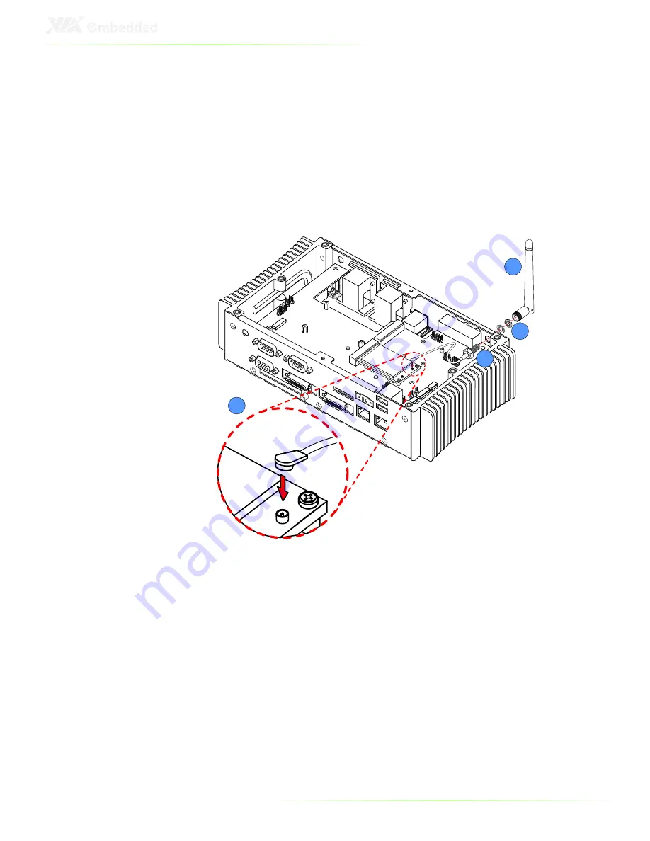
Step 6
Insert the antenna cable into the Mobile Broadband antenna hole
from the inside. Make sure the flat side of the antenna jack
matches the flat side of the antenna hole.
Step 7
Secure the Mobile Broadband antenna jack to the chassis with the
toothed washer and nut.
6
8
7
9
Step 8
Connect the other end of the WLAN antenna cable to the micro-
RF connector on the Mobile Broadband module.
Step 9
Attach the antenna provided with the Mobile Broadband kit to the
Mobile Broadband antenna jack.
Summary of Contents for ART-5450
Page 12: ...XII ...
Page 13: ...1 1 Product Overview ...
Page 21: ...9 ART 5450 DIMENSIONS ...
Page 49: ...37 Step 2 Fasten the mounting brackets to the bottom side of the ART 5450 chassis as shown ...
Page 50: ...38 Step 3 Secure both mounting brackets to the wall table with four screws ...
Page 52: ...40 Step 4 Connect the power module to the power source using the provided cable ...
Page 54: ...42 Power Input Connector Pin Signal 1 IGN2 2 GND 3 DC 10 30V 4 ACC 5 GND 6 DC 10 30V 1 3 4 6 ...
Page 61: ...49 5 BIOS Setup This chapter gives a detailed explanation of the BIOS setup functions ...
Page 71: ...59 Summary Screen Show Show summary screen Settings Disabled Enabled ...
Page 100: ......
Page 101: ...89 6 Driver Installation ...


