VIA Mobile360 M820 User Manual
viii
List of Figures
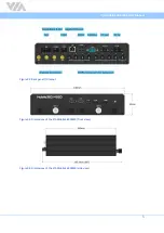
Figure 01: Front panel I/O layout
Figure 02: Back panel I/O layout
Figure 03: Dimensions of the VIA Mobile360 M820 (front view)
.........................................................................
Figure 04: Dimensions of the VIA Mobile360 M820 (side view)
..........................................................................
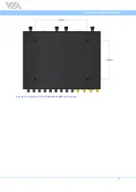
Figure 05: Dimensions of the VIA Mobile360 M820 (bottom view)
..................................................................... 6
Figure 07: USB 3.0 port diagram
Figure 08: Micro USB 2.0 port diagram
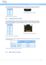
Figure 09: Gigabit Ethernet port diagram
Figure 10: Micro SD card slot diagram
Figure 11: SIM card slot diagram
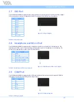
Figure 13: Headphone and Mic-in port diagram
................................................................................................ 10
Figure 15: CAN bus port diagram
Figure 16: FAKRA connector diagram
Figure 17: Power button diagram
Figure 19: DC-out jack diagram
Figure 20: Wi-Fi antenna connectors diagram
Figure 21: GPS and 4G antenna connectors diagram
......................................................................................... 13
Figure 22: MiniPCIe slot diagram
Figure 23: Unlocking the SATA HDD/SSD bay
....................................................................................................
Figure 24: Removing the SATA HDD/SSD bays
....................................................................................................
Figure 25: Installing the 2.5" SATA HDD/SSD
Figure 26: Reinstalling the SATA HDD/SSD bays
................................................................................................. 16
Figure 27: Installing the Wi-Fi antennas
Figure 28: Installing the GPS antenna
Figure 29: Connecting the FOV camera to the FAKRA cable
............................................................................... 18
Figure 30: Connecting the FAKRA cable to the FAKRA connector
...................................................................... 18
Figure 31: Unplugging the FAKRA cable
Figure 33: VIA Mobile360 M820 and IGN connection method diagram
............................................................ 20
Figure 34: Connecting the battery cables onto the Phoenix plug to DC jack
..................................................... 21
Figure 35: Connecting the Phoenix plug to DC jack
............................................................................................ 21
Figure 36: Unscrewing the bottom plate cover
Figure 37: Removing the bottom plate cover
Figure 38: Installing the mobile broadband module
.......................................................................................... 24
Figure 39: Connecting the 4G antenna cable to the micro-RF connector on the module
..................................
Figure 40: Installing the 4G antenna
Figure 41: Attaching the internal bracket to the external bracket
...................................................................... 26
Figure 42: Installing the double-sided adhesive tape on the camera bracket
.................................................... 26
Figure 43: Installing the FOV-190 camera on the camera bracket
......................................................................
Figure 44: Removing the double-sided adhesive tape protective cover
............................................................


