background image

Chapter 3

3-6

Date

The date format is <day><month> <date> <year>.

day

 Day of the week, from Sun to Sat, determined by BIOS.  Read-only.

month

 The month from Jan. through Dec.

date 

The date from 1 to 31 can be keyed by numeric function keys.

year

 The year, depends on the year of the BIOS

Time

The time format is <hour> <minute> <second>.

IDE Primary/Secondary Master/Slave

Press PgUp/<+> or PgDn/<-> to select Manual, None, Auto type. Note that the
specifications of your drive must match with the drive table. The hard disk will
not work properly if you enter improper information for this category. If your
hard disk drive type is not matched or listed, you can use Manual to define
your own drive type manually.

If you select Manual, related information is asked to be entered to the follow-

Standard CMOS Features

The Standard CMOS Features Menu is divided into 10 categories.  Each cat-
egory includes one or more setup items. Use the arrow keys to highlight the
item and then use the <PgUp> or <PgDn> keys to select the value you want in
each item.

Summary of Contents for VIA P4XB-RA

Page 1: ...i VIA Mainboard User s Manual VIA P4XB SA VIA P4XB RA Version 1 0 November 28 2001 ...

Page 2: ...acy of the content of this manual However it is possible that it may contain technical inaccuracies or typographical or other errors VIA will assume no liability for any inaccuracy found in this publication nor for damages direct indirect incidental consequential or otherwise that may result from such an inaccuracy including without limitation loss of data or profits VIA provides this manual as is...

Page 3: ... energy and if not installed and used in accor dance with the instruction manual may cause harmful interference to radio communications Operation of this equipment in a residential area is likely to cause harmful interference in which case the user will be required to correct the interference at his own expense Notice 1 The changes or modifications not expressly approved by the party respon sible ...

Page 4: ...the voltage of the power source and adjust properly 110 220V before connecting the equipment to the power inlet 7 Place the power cord such a way that people cannot step on it Do not place anything over the power cord 8 Always Unplug the Power Cord before inserting any add on card or module 9 All cautions and warnings on the equipment should be noted 10 Never pour any liquid into the opening Doing...

Page 5: ...r s manual 1 x Floppy ribbon cable 1 x ATA 66 100 Hard drive ribbon cable 2 are included with the VIA P4XB RA 1 x 2 Port USB Module 1 x Driver Utilities CD 1 x User s Manual for Promise FastTrak 100 Lite RAID Controller with VIA P4XB RA only ...

Page 6: ...7 ATX 20 Pin Power Connector JWR1 2 7 ATX 12V Power Connector JPW1 2 7 Back Panel 2 8 Mouse Connector JKBMS1 2 8 Keyboard Connector JKBMS1 2 8 USB Connectors 2 9 Parallel Port Connector LPT1 2 9 Serial Port Connectors COM A COM B 2 10 Joystick MIDI Connector 2 10 Audio Port Connectors 2 10 Connectors 2 11 Floppy Disk Drive Connector FDD1 2 11 IrDA Infrared Module Connector IR1 2 11 Hard Disk Conne...

Page 7: ...Jumper JP1 2 20 Slots 2 21 AGP Accelerated Graphics Port Slot 2 21 PCI Slots 2 21 CNR Communication Network Riser 2 21 PCI Interrupt Request Routing 2 22 Chapter 3 BIOS Setup 3 1 Entering Setup 3 2 Control Keys 3 2 Getting Help 3 3 The Main Menu 3 4 Standard CMOS Features 3 6 Advanced BIOS Features 3 8 Advanced Chipset Features 3 11 Integrated Peripherals 3 16 Power Management Setup 3 22 PNP PCI C...

Page 8: ...et Supervisor User Password 3 33 Save Exit Setup 3 35 Exit Without Saving 3 36 Chapter 4 Driver Setup 4 1 VIA Apollo P4X266A Chipset Drivers 4 2 C Media CMI8738 Audio Driver P4XB RA only 4 7 Realtek ALC201A Audio Driver P4XB SA only 4 9 ...

Page 9: ...m VIA s ad vanced V Link controller brings optimal system effi ciency by effectively doubling bandwidth between the chipset s north and south bridges Designed for the latest 478 pin Pentium 4 processors these ATX sized mainboards are the perfect choice for Pentium 4 based high performance PCs servers and workstations This chapter includes the following sections Mainboard Specifications 1 2 Mainboa...

Page 10: ...7 audio Ultra DMA 33 66 100 master mode PCI EIDE controller ACPI 1 0B and PCI Bus Power Management 1 1 compliant Main Memory 3 x 184 pin DDR DIMM slots Supports up to 3GB of DDR266 SDRAM PC2100 PC1600 Supports 2 5v DDR266 SDRAM Slots 1 x AGP Accelerated Graphics Port 4X slot 5 x PCI 2 2 32 bit PCI bus slots supports 3 3v 5v PCI bus interface 1 x CNR Communication Network Riser slot OnboardIDE Inte...

Page 11: ...lus 2 pin headers for up to 4 additional connections 1 x IrDA connector for SIR CIR ASKIR HPSIR 1 x Game MIDI port Audio H W C Media CMI8738 PCI 6ch supports 2 4 6 channel speaker VIA P4XB RAonly S W Realtek ALC201A AC 97 Codec BIOS Award Plug Play BIOS Desktop Management Interface DMI function which records your mainboard specifications Dimension ATX Form Factor 30 5cmx22 5cm Mounting 6 mounting ...

Page 12: ...Chapter 1 1 4 Layout VIA P4XB RA VIA P4XB SA Mainboards ...

Page 13: ...r See p 2 11 IDE1 IDE2 Hard disk connectors See p 2 12 J3 CD in connector See p 2 13 J4 Aux line in connector See p 2 13 J5 Modem in connector See p 2 13 CFAN2 SFAN1 Fan power connectors See p 2 14 JFP1 JFP2 Case connector See p 2 15 JAUD Front panel audio connector See p 2 16 JMDM1 Wake on ring connector See p 2 17 JGS1 Power saving switch connector See p 2 17 USB3 USB4 Connecting to USB devices ...

Page 14: ...res Some components may be damaged if they are installed incorrectly It is recommended to use a grounded wrist strap before handling computer components Static electricity can damage some components This chapter contains the following sections CPU Installation 2 2 Memory Installation 2 5 Power Supply 2 7 Back Panel 2 8 Connectors 2 11 Jumpers 2 19 Slots 2 21 Chapter 2 Installation Installation 2 ...

Page 15: ...ealer to purchase and install them before turning on the computer CPU Installation Overheating will cause serious damage to the CPU and system Ensure the cooling fan and heatsink work properly to protect the CPU from overheating WARNING 1 Pull the lever sideways away from the socket Then raise the lever up to a 90 degree angle 2 Look for the dot cut edge The dot cut edge should point to wards the ...

Page 16: ...CPU core speed Host Clock x Core Bus ratio 100MHzx14 1 4GHz Overclocking This mainboard is designed to support overclocking However please make sure your components are able to tolerate such abnor mal settings before overclocking Any attempt to operate beyond product specifications is not recommended We do not guarantee the damages or risks caused by inadequate operation or operation be yond produ...

Page 17: ... connector on the mainboard 3 Mount the fan on top of the heatsink Press down the fan firmly until its four clips become wedged in the holes of the retention mechanism 4 Press the two levers down to secure the fan Each lever can be pressed down in only ONE direction fan power cable levers ...

Page 18: ... Conventional SDRAM only uses the rising edge of the clock t o t r a n s f e r d a t a Therefore conventional SDRAM is called SDR Single Data Rate SDRAM DDR SDRAM uses 2 5 volts as opposed to 3 3 volts used in SDR SDRAM and requires 184 pin DIMM modules rather than 168 pin DIMM modules used by SDR SDRAM DDR266 SDRAM is also known as SDRAM II DDR DRAM and DSDRAM Double Speed DRAM Two types of DDR a...

Page 19: ... o ta l M e m o r y S lo t 1 B a n k 0 B a n k 1 6 4 M B 1 2 8 M B 2 5 6 M B 5 1 2 M B 1 G B 6 4 M B 1 G B S lo t 2 B a n k 2 B a n k 3 6 4 M B 1 2 8 M B 2 5 6 M B 5 1 2 M B 1 G B 6 4 M B 1 G B S lo t 3 B a n k 4 B a n k 5 6 4 M B 1 2 8 M B 2 5 6 M B 5 1 2 M B 1 G B 6 4 M B 1 G B M a x im u m S y s te m M e m o r y S u p p o r te d 6 4 M B 3 G B 1 The DDR DIMM module has only one notch on the cent...

Page 20: ...supply connector is in serted on the mainboard The VIA P4XB RA and VIA P4XB SA mainboards require an ATX power supply for powering the system Before inserting the power supply connector always make sure that all components are installed properly to ensure that no damage will be caused ATX 12V Power Connector JPW1 This 12V power connector is used to provide power to the CPU PIN SIGNAL 1 GND 2 GND 3...

Page 21: ...se connector for attaching a PS 2 mouse You can plug a PS 2 mouse di rectly into this connector The connec tor location and pin assignments are as follows PS 2 Mouse 6 pin Female 2 1 3 4 5 6 PS 2 Keyboard 6 pin Female 2 1 3 4 5 6 PIN SIGNAL DESCRIPTION 1 MouseDATA MouseDATA 2 NC Noconnection 3 GND Ground 4 VCC 5V 5 Mouse Clock Mouse clock 6 NC Noconnection Pin Definition PIN SIGNAL DESCRIPTION 1 K...

Page 22: ...lel Port Connector LPT1 The mainboard provides a 25 pin female connector for LPT parallel port A parallel port is a standard printer port that supports Enhanced Parallel Port EPP and Extended Capabilities Parallel Port ECP modes 13 1 14 25 PIN SIGNAL DESCRIPTION 1 STROBE Strobe 2 DATA0 Data0 3 DATA1 Data1 4 DATA2 Data2 5 DATA3 Data3 6 DATA4 Data4 7 DATA5 Data5 8 DATA6 Data6 9 DATA7 Data7 10 ACK Ac...

Page 23: ...oSend 8 CTS Clear To Send 9 RI RingIndicate 9 Pin Male DIN Connectors Pin Definition Joystick MIDI Connector You can connect a joystick or game pad to this connector Audio Port Connectors Line Out is a connector for speakers or headphones The Line In connector can be used for an external CD player tape player or other audio devices The Mic in connector is for connecting microphones 1 8 Stereo Audi...

Page 24: ... Drive Connector FDD1 The standard floppy disk drive connector supports 360K 720K 1 2M 1 44M and 2 88M floppy disk types Connectors IrDA Infrared Module Connector IR1 This connector allows you to connect an IrDA Infrared module You must configure the setting through the BIOS setup to activate the IR function PIN SIGNAL 1 VCC 2 NC 3 IRRX 4 GND 5 IRTX Pin Definition IR1 1 5 ...

Page 25: ...utilize the provided IDE hard disk cable IDE1 PrimaryIDEConnector The first hard drive should always be connected to IDE1 IDE1 can connect a Master and a Slave drive You must configure the second hard drive to Slave mode by setting the jumper accordingly IDE2 Secondary IDE Connector IDE2 can also connect a Master and a Slave drive TIP If you install two hard disks on cable you must config ure the ...

Page 26: ...r is for the CD ROM audio connector Aux Line In Connector J4 This connector is for a DVD add on card with Line in connector Modem In Connector J5 This connector is for a modem with internal audio connector J4 GND R L J5 GND Phone_In Mono_Out J3 GND R L ...

Page 27: ...intain system cooling When connecting the wire to the connectors always be aware that the red wire is the Positive and should be connected to the 12V The black wire is Ground and should be connected to GND Note Always consult the vendor for proper CPU cooling fan SFAN1 SENSOR 12V GND CFAN2 SENSOR 12V GND ...

Page 28: ...ting while the HDD is working You can connect the Reset Switch from the system case to this pin PowerLED The Power LED is lit while the system power is on Speaker The speaker from the system case is connected to this pin If on board Buzzer is available Short pin 14 15 On board Buzzer Enabled Open pin 14 15 On board Buzzer Disabled HDDLED HDD LED shows the activity of a hard disk drive Avoid turnin...

Page 29: ...udio circuits 3 AUD_MIC_BIAS Microphone power 4 AUD_VCC Filtered 5V used by analog audio circuits 5 AUD_FPOUT_R Right channel audio signal to front panel 6 AUD_RET_R Right channel audio signal return from front panel 7 HP_ON Reserved for future use to control headphone amplifier 8 KEY No pin 9 AUD_FPOUT_L Left channel audio signal to front panel 10 AUD_RET_L Left channel audio signal return from f...

Page 30: ...n The connector will power up the system when a signal is received through the modem card JMDM1 NC MDM_WAKEUP 5VSB 1 GND NC Power Saving Switch Connector JGS1 Attach a power saving switch to this connector Pressing the switch once will enter the system into the sleep suspend state Pressing any key will wake up the system JGS1 ...

Page 31: ... GND 8 GND 9 NC Key 10 GND USB4 Pin Definition USB3 1 9 2 10 USB4 12345678 12345678 12345678 1 9 2 10 Pin Description Pin Description 1 VCC 2 GND 3 USB0 4 GND 5 USB0 6 USB1 7 GND 8 USB1 9 GND 10 VCC USB3 Pin Definition NOTE The bundled 9 pin cable is for use with USB4 only Incorrect use will cause damage If installing additional USB cables other than those bundled please be sure to follow the pin ...

Page 32: ...rom the CMOS RAM use the J7 Clear CMOS Jumper Follow the instructions below to clear the data Jumpers The VIA P4XB RA and P4XB SA mainboards provide jumpers for setting the mainboard s functions This section will explain how to change settings for your mainboard s functions through the use of the jumpers Clear CMOS 3 1 Keep CMOS 3 1 You can clear the CMOS by shorting 2 3 pin while the system is of...

Page 33: ...dio codec the system will use the onboard codec as the PRIMARY audio adapter and the installed CNR card as the SECONDARY one However some types of CNR cards cannot be set to secondary mode In this case the onboard audio codec must be disabled to resolve the system conflict 1 3 Enable onboard audio codec Disable onboard audio codec 1 3 JP1 1 ...

Page 34: ...our needs When adding or removing PCI expansion cards ensure that you unplug the power supply first Meanwhile read the documentation for the expansion card to make any necessary hardware or software settings for the expansion card such as jumpers switches or BIOS configuration CNR Communication Network Riser The CNR slot allows you to insert a CNR expansion card CNR is a specially designed network...

Page 35: ...roprocessor The PCI IRQ pins are typically connected to the PCI bus INT A INT D pins as follows Order 1 Order 2 Order 3 Order 4 PCI Slot 1 INT A INT B INT C INT D PCI Slot 2 INT B INT C INT D INT A PCI Slot 3 INT D INT A INT B INT C PCI Slot 4 INT D INT A INT B INT C PCI Slot 5 INT A INT B INT C INT D ...

Page 36: ... 3 6 Advanced BIOS Features 3 8 Advanced Chipset Features 3 11 Integrated Peripherals 3 16 Power Management Setup 3 22 PNP PCI Configurations 3 26 PC Health Status 3 28 Frequency Voltage Control 3 29 Load High Performance Defaults 3 31 Load Optimized Defaults 3 32 Set Supervisor User Password 3 33 Save Exit Setup 3 35 Exit Without Saving 3 36 ...

Page 37: ...Alt and Delete keys n Move to the previous item p Move to the next item m Move to the item in the left hand o Move to the item in the right hand Enter Select the item Esc Jumps to the Exit menu or returns to the main menu from a submenu PU Increase the numeric value or make changes PD Decrease the numeric value or make changes F1 General help only for Status Page Setup Menu and Option Page Setup M...

Page 38: ...field to field within a sub menu If you want to return to the main menu just press Esc GeneralHelp F1 The BIOS setup program provides a General Help screen You can call up this screen from any menu by simply pressing F1 The Help screen lists the appropriate keys to use and the possible selections for the highlighted item Press Esc to exit the Help screen After entering the Setup menu the first men...

Page 39: ...IntegratedPeripherals Use this menu to specify your settings for integrated peripherals PowerManagementSetup Use this menu to specify your settings for power management PnP PCIConfigurations This entry appears if your system supports PnP PCI Once you enter Award BIOS CMOS Setup Utility the Main Menu Figure 1 will appear on the screen The Main Menu allows you to select from twelve setup functions a...

Page 40: ...d the BIOS values for the best system performance but the system stability may be affected LoadOptimizedDefaults Use this menu to load factory default settings into the BIOS for optimal and stable system operations Supervisor UserPassword Use this menu to set User and Supervisor Passwords Save ExitSetup Save CMOS value changes to CMOS and exit setup ExitWithoutSaving Abandon all CMOS value changes...

Page 41: ...te that the specifications of your drive must match with the drive table The hard disk will not work properly if you enter improper information for this category If your hard disk drive type is not matched or listed you can use Manual to define your own drive type manually If you select Manual related information is asked to be entered to the follow Standard CMOS Features The Standard CMOS Feature...

Page 42: ...ctor Number of sectors Drive A B This item allows you to set the type of floppy drives installed Available options are None 360K 5 25 in 1 2M 5 25 in 720K 3 5 in 1 44M 3 5 in 2 88M 3 5 in Video The setting controls the type of video adapter used for the primary monitor of the system Available options are EGA VGA CGA 40 CGA 80 and Mono HaltOn The setting determines whether the system will stop if a...

Page 43: ...rnal L2 cache Settings Enabled and Disabled CPU L2 Cache ECC Checking This setting allows you to enable or disable the ECC Error Correcting Code feature for error detection and correction when data passes through L2 cache memory Setting options Enabled and Disabled Quick Power On Self Test The option speeds up Power On Self Test POST after you power on the computer When setting the item to Enabled...

Page 44: ...nd Third boot device RAID SCSI Boot Order This setting determines the boot order of the onboard IDE RAID device and the external SCSI device If no SCSI device is connected the system will auto matically boot the onboard IDE RAID device Setting options RAID SCSI SCSI RAID Swap FloppyDrive Setting to Enabled will swap floppy drives A and B BootUpFloppySeek Setting to Enabled will make BIOS seek flop...

Page 45: ...eleration begins Settings 250 500 750 and 1000 SecurityOption This specifies the type of BIOS password protection that is implemented Set tings are described below OS Select For DRAM 64MB This allows you to run the OS 2 operating system with DRAM greater than 64MB Setting options Non OS2 OS2 Full Screen LOGO Show This setting enables disables the Full Screen LOGO Show capability VideoBIOSCacheable...

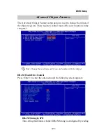
Page 46: ...ters control most of the system options in the computer Advanced Chipset Features DRAMClock DriveControl Press Enter to enter the sub menu and the following screen appears DRAMTimingbySPD This setting determines whether DRAM timing is configured by reading Note Change these settings only if you are familiar with the chipset ...

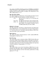
Page 47: ...etermines the timing delay before SDRAM starts a read command after receiving it Setting options 2 2 5 clock cycles Auto 2 increases system performance while 3 pro vides more stable system performance BankInterleave This setting determines the bank interleave for the installed SDRAM Setting options Disabled Auto RowPrecharge This setting allows you to select the number of DRAM clocks allocated for...

Page 48: ...ows you to set the size for Burst Length for DRAM The bigger the sizes the faster the system addresses memory Setting options 4 8 Auto DRAMCommandRate This setting controls the DRAM command rate Selecting 1T allows DRAM signal controller to run at 1T T clock cycles rate Selecting 2T makes DRAM signal controller run at 2T rate 1T is faster than 2T Setting options 2T 1T AGP P2P Bridge Control Press ...

Page 49: ...to select Auto to avoid causing any system error Setting options Auto Manual AGP Fast Write This setting enables disables the AGP Fast Write feature The Fast Write technology allows CPU to write directly into the graphics card without passing anything through system memory and improves 4X speed accordingly Select Enabled only when your AGP card supports the feature Setting options Enabled Disabled...

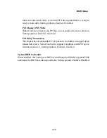
Page 50: ...it state Setting options Enabled Disabled PCIDelayTransaction The chipset has an embedded 32 bit posted write buffer to support delay transaction cycles Select Enabled to support compliance with PCI speci fication version 2 1 Setting options Enabled Disabled System BIOS Cacheable When enabled this setting sets BIOS write through at DRAM segment F000 and makes the BIOS execution speed faster Settin...

Page 51: ...nboardPromiseChip optional This setting enables disables the onboard IDE RAID controller Setting options Enabled Disabled OnboardAudioChip optional This setting enables disables the onboard C Media audio chip Setting options Enabled Disabled ...

Page 52: ...reased performance In Auto mode BIOS auto matically determines the best mode for each IDE device Primary SecondaryMaster SlaveUDMA Ultra DMA implementation is possible only if your IDE device supports it and your operating environment contains a DMA driver If both your hard drive and software support Ultra DMA 33 select Auto to enable BIOS support Setting options Auto Disabled IDEHDDBlockMode This...

Page 53: ...ntroller if you want to use other controller cards to connect an audio device Setting options Auto Disabled VIA 3068MC97Modem Auto allows the mainboard to detect whether a modem is used If a modem is used the onboard VIA MC 97 Modem Codec 97 controller will be enabled if not it is disabled Disable the controller if you want to use other controller cards to connect to a modem Setting options Auto D...

Page 54: ...for the onboard Serial Port A Serial Port B Selecting Auto allows BIOS to automatically determine the correct base I O port address Settings Disabled 3F8 IRQ4 2F8 IRQ3 3E8 IRQ4 2E8 IRQ3 and Auto UARTModeSelect The field allows you to specify the operation mode for serial port COM B Settings are Normal RS 232CSerialPort IrDA IrDA compliant Serial Infrared Port ASKIR Amplitude Shift Keyed Infrared P...

Page 55: ...s and IRQ of the onboard parallel port Settings 378 IRQ7 278 IRQ5 3BC IRQ7 and Disabled ParallelPortMode SPP Standard Parallel Port EPP Enhanced Parallel Port ECP Extended Capability Port ECP EPP Extended Capability Port Enhanced Parallel Port SPP EPP ECP ECP EPP To operate the onboard parallel port as Standard Parallel Port only choose SPP To operate the onboard parallel port in the EPP mode simu...

Page 56: ...re or interrupt occurs GamePortAddress MidiPortAddress This setting disables or assigns an address for the onboard game midi port MidiPortIRQ This setting specifies an IRQ for the onboard midi port Init Display First This setting specifies which VGA card is your primary graphics adapter Set ting options PCI Slot and AGP OnChipUSBController This setting allows you to activate the onchip USB control...

Page 57: ... item specifies the power saving modes for ACPI function Options are S1 POS The S1 sleep mode is a low power state In this state no system context CPU or chipset is lost and hardware maintains all system context S3 STR The S3 sleep mode is a power down state in which power is supplied only to essential components such as main memory and wake capable devices and all system con text is saved to main...

Page 58: ... system inactivity the CPU clock runs at slower speed while all other devices still operate at full speed Settings are Disable 1 Min 2 Min 4 Min 6 Min 8 Min 10 Min 20 Min 30 Min 40 Min and 1 Hour SuspendMode After the selected period of system inactivity all devices except the CPU shut off Settings are Disabled 1 Min 2 Min 4 Min 8 Min 12 Min 20 Min 30 Min 40 Min and 1 Hour PMControlbyAPM Setting t...

Page 59: ...anges its color to indicate the sleep state IRQ EventActivityDetect Press Enter to enter the sub menu and the following screen appears PS2KB Wakeup Select PS2KB Wakeup from S3 S4 S5 PS2MS Wakeup from S3 S4 S5 USB Resume from S3 VGA LPT COM HDD FDD PCI Master PowerOn by PCI Card Wake Up On LAN Ring These fields specify whether the system will be awakened from power saving modes when activity or inp...

Page 60: ...to wake up from power saving modes if activity is detected from any enabled IRQ channels IRQ3 IRQ15 Enables or disables the monitoring of the specified IRQ line If set to Enabled the activity of the specified IRQ line will prevent the system from entering power saving modes or awaken it from power saving modes Note IRQ Interrupt Request lines are system resources allocated to I O devices When an I...

Page 61: ...ds will be initialized by the PnP operating system like Windows 95 or 98 When set to No BIOS will initialize all the PnP cards So select Yes if the operating system is Plug Play aware Reset Configuration Data Normally you leave this field Disabled Select Enabled to reset Extended Sys tem Configuration Data ESCD when you exit Setup if you have installed a new add on and the system reconfiguration h...

Page 62: ...g on different buses can handle data from the CPU on each set of palette registers on every video device Bit 5 of the command register in the PCI device configuration space is the VGA Palette Snoop bit 0 is disabled For example if there are two VGA devices in the computer one PCI and one ISA and the The setting must be set to Enabled if any ISA bus adapter in the system requires VGA palette snoopi...

Page 63: ...he upper limit preset in this setting the warn ing mechanism will be activated This helps you to prevent the CPU overheat problem Current System CPU Temperature Current System CPU Fan Vcore 3 3V 5V 12V 12V 5V VBAT V 5VSB V These items display the current status of all of the monitored hardware de vices components such as CPU voltages temperatures and all fans speeds ...

Page 64: ...unction reduces the EMI generated by modulating the pulses so that the spikes of the pulses are reduced to flatter curves If you do not have any EMI problem leave the setting at Disabled for optimal system stability and performance But if you are plagued by EMI setting to Enabled for EMI reduction Remember to disable Spread Spectrum if you are overclocking be cause even a 0 25 jitter can introduce...

Page 65: ...ve to the external or motherboard clock speed CPUVcoreRegulator This setting allows you to adjust the CPU core voltage from 0 025V to 0 100V at 0 025 increment Please note that it may be dangerous to adjust the Vcore over 10 DRAMVoltage This setting allows you to set the appropriate DRAM voltage Setting options 2 50V 2 56V 2 60V 2 65V ...

Page 66: ...hen you select Load High Performance Defaults a message as below appears Pressing Y loads the default BIOS values that enable the best system perfor mance better than the Optimized Defaults but may result in the instability of the system Load High Performance Defaults This setting is for experienced or overclocking users only If the system crashes or hangs after enabling the feature please CLEAR C...

Page 67: ...mized Defaults are the default values also set by the mainboard manufacturer for both optimized and stable perform ance of the mainboard When you select Load Optimized Defaults a message as below appears Pressing Y loads the default values that are factory settings for optimal and stable system performance Load Optimized Defaults ...

Page 68: ...ill show up confirming the password will be disabled Once the password is disabled the system will boot and you can enter Setup without entering any password When a password has been set you will be prompted to enter it every time you try to enter Setup This prevents an unauthorized person from changing any part of your system configuration Additionally when a password is enabled you can also have...

Page 69: ... Supervisor password Can enter and change the settings of the setup menus User password Can only enter but do not have the right to change the settings of the setup menus entry to Setup If set to Setup password prompt only occurs when trying to enter Setup ...

Page 70: ...t the Setup menu you can select this option to save the changes and quit A message as below will appear on the screen Typing Y will allow you to quit the Setup Utility and save the user setup changes to RTC CMOS Typing N will return to the Setup Utility ...

Page 71: ... to quit the Setup menu you can select this option to abandon the changes A message as below will appear on the screen Typing Y will allow you to quit the Setup Utility without saving any changes to RTC CMOS Typing N will return to the Setup Utility ...

Page 72: ...MI8738 AD1885 AC 97 audio drivers It consists of the following topics Note You must install VIA chipset drivers first before installing other drivers like audio or VGA drivers VIA Apollo P4X266A Chipset Drivers 4 2 C Media CMI8738 Audio Driver 4 7 Realtek ALC201A Audio Driver 4 9 Chapter 4 Driver Setup Driver Setup 4 ...

Page 73: ...egrated Ultra DMA 33 66 100 master mode PCI EIDE controller Full featured Accelerated Graphics Port AGP controller Supports 533MHz 8x and 266MHz 4x transfer modes for AD and SBA signaling Pseudo synchronous with the host CPU bus with optimal skew control Windows 95 OSR 2 VXD and integrated Windows 98 NT5 miniport driver support System Requirements Computer Intel Pentium 4 processors Monitor VGA Su...

Page 74: ...k on Next 6 The setup program will request you to choose Install VIA ATAPI Ven dor Support Driver Select Install and click Next to continue 7 Select Click to enable DMA Mode and click Next to continue 8 The setup program will request you to choose Install VIA AGP VxD in Turbo mode Install VIA AGP VxD in normal mode or Uninstall VIA AGP VxD Select Install VIA AGP VxD in turbo mode and click on Next...

Page 75: ...DE Bus Driver dialog box Select Install and then click on Next 7 The screen will show a VIA AGP Driver 4 XX dialog box Select Install AGP 4X 133 driver and click Next 8 The setup program will request you to choose whether to restart the computer or not Please select Yes I want to restart my computer now and click Finish The computer will restart and finish the VIA Chipset Drivers installation One ...

Page 76: ...Next 7 The screen will show a VIA AGP Driver 4 XX dialog box Select Install AGP 4X 133 driver and click Next 8 The setup program will request you to choose whether to restart the computer or not Please select Yes I want to restart my computer now and click Finish The computer will restart and finish the VIA Chipset Drivers installation One Touch Setup In Windows ME you probably will see the One To...

Page 77: ... on VIA Chipset Drivers and the screen will show VIA Service Pack 4 XX 4 Click Next and the screen will show the VIA Service Pack 1 README dialog box 5 Click Yes to proceed and then select Install to enable Ultra DMA for IDEDriver 6 The Choose Destination Location dialog box appears Click Next 7 The Select Program Folder dialog box appears Click Next 8 Click on Yes I want to restart my computer an...

Page 78: ...l duplex playback and recording Built in 16 bit CODEC HRTF 3D positional audio supporting both DirectSound 3D A3D interfaces Also supports earphones 2 4 6 channel speakers mode Support Windows 98 Windows 2000 and Windows NT 4 0 Built in 32 OHM earphone buffer MPU 401 Game Midi port and legacy audio SB Pro support Downloadable Wave Table Synthesizer supporting Direct Music Stereo Mixer Stereo analo...

Page 79: ...Setting and select the Con trol Panel 2 Double click Multimedia 3 Select Devices and press Add 4 Select Unlisted or Updated Driver in List of Drivers 5 Specify the drive path where NT drivers are in such as D NT40 DRV 6 Select C Media CM8738 and press OK 7 Select proper I O value 8 Press OK 9 Restart the system when being asked 10 Now you have already installed the PCI Audio Adapter under Microsof...

Page 80: ...on for PCs Features AC 97 2 2 Compatible WHQL Compliant High Performance Converter Technology 18 bit Stereo Full Duplex CODEC with Independent Variable Sampling Rate Four Analog Line Level Stereo Inputs for Connection from LINE CD VIDEOandAUX Two Analog Line Level Stereo Inputs for Speakerphone and PC BEEP Two MIC Inputs w Software Selectable High Quality Differential CD Input True Stereo Line Lev...

Page 81: ...rive 2 The CD will auto run and the setup screen will appear 3 Click on ADVANCED Sound Drivers and follow the on screen instruc tions to complete the installation 4 After completion of the installation please restart Windows system for new driver installation The system will install the device drivers automatically ...

Reviews: