background image


1.3 

Boiler technical data 

 
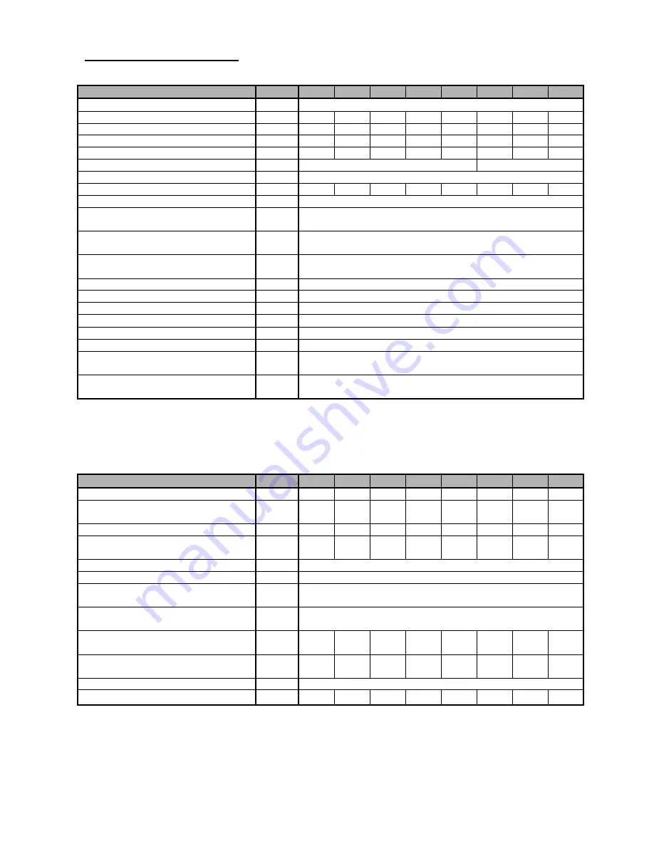
Tab. no. 1  Dimensions, technical data  

Number of sections 

pc 

10 

Boiler class according to EN 303 - 5 

Combustion chamber volume 

23,6 

37,6 

51,6 

65,6 

79,6 

93,6 

107,6  121,6 

Water space volume 

39,5 

49,3 

59,1 

68,9 

78,7 

88,5 

98 

107,8 

Weight 

kg 

262 

312 

362 

412 

462 

512 

562 

612 

Combustion chamber depth  

mm 

220 

330 

440 

550 

660 

770 

880 

990 

Diameter of smoke socket 

mm 

156


176


Boiler dimensions: height x width 

mm 

1161 x 665 

depth L 

mm 

714 

825 

936 

1047 

1158 

1269 

1380 

1491 

Filling opening dimensions 

mm 

245x 195 

Maximum working water overpressure  

kPa 

(bar) 

400  

(4) 

Minimum working water overpressure 

kPa 

(bar) 

50  

(0,5) 

Testing water overpressure 

kPa 

(bar) 

800  

(8) 

Boiler hydraulic loss 

See Fig. no. 1 

Minimum output water temperature 

°C 

60 

Control range of water temperature 

°C 

60 – 85 

Noise level  

dB 

Does not exceed the level 65 dB (A) 

Boiler connections – heating water 

“ 

6/4 

– return water 

“ 

6/4 

Cooling water temperature for 
equipment for surplus heat withdaral 

°C 

5 – 20 

Cooling water overpressure for 
equipment for surplus heat withdaral 

kPa 

(bar) 

200 – 600  

(2-6) 


Tab. no. 2  Technical data – hard coal as fuel 

granularity 20 – 40 mm, fuel moisture max. 15 % 
calorific value of fuel: 14 – 20 MJ.kg

-1


Number of sections 

pc 

10 

Nominal heat output  

kW 

13 

19 

25 

31 

37 

43 

49 

55 

Fuel consumption at nominal heat 
output  

kg.h

-1


2,60 

3,80 

5,00 

6,20 

7,40 

8,60 

9,80 

11,00 

Minimum heat output  

kW 

3,9 

5,7 

7,5 

9,3 

11,1 

12,9 

14,7 

16,5 

Fuel consumption at minimum heat 
output  

kg.h

-1


0,79 

1,15 

1,51 

1,87 

2,23 

2,60 

2,96 

3,32 

Fuel efficiency 

MJ.kg

-1


19,81 

Burning time at nominal output 


hour 

Flue gases temperature at nominal 
heat output  

°C 

220 – 250 

Flue gases temperature at minimum 
heat output  

°C 

110 – 120 

Flue gases mass flow rate at nominal 
output  

g.s

-1


10,65  15,57  20,49  25,41  30,33  35,24  40,16  45,08 

Flue gases mass flow rate at 
minimum heat output  

g.s

-1


4,92 

7,19 

9,46 

11,73  14,00  16,27  18,54  20,81 

Efficiency 

78 

Required chimney draught 

mbar 

0,13 

0,14 

0,15 

0,20 

0,22 

0,28 

0,30 

0,32 


Summary of Contents for Hercules U 24

Page 1: ...Hercules U26 Návod k obsluze VIADRUS HERCULES U 24 MANUAL FOR BOILER OPERATION AND INSTALLATION ...

Page 2: ...ories 12 2 5 Assembly technique 12 2 6 Boiler commissioning 17 2 6 1 Verification activities before commissioning 17 2 6 2 Boiler commissioning 17 2 7 Control and safety elements 17 2 8 Equipment for surplus heat withdrawal 17 2 9 Equipment for heat withdrawal accumulation tank 19 3 Manual for operation 20 3 1 Boiler operation by user 20 3 2 Boiler cleaning maintenance 22 3 3 IMPORTANT NOTICE 23 4...

Page 3: ...ion in independent tenements for smaller residential premises and leisure amenities Bigger sizes of boiler 4 10 sections meet the demands on heating of family houses shops schools etc The boiler is manufactured as a hot water boiler with both natural and forced heating water circulation and working overpressure up to 400 kPa 4 bar Before dispatch the boiler is tested for tightness by applying 800 ...

Page 4: ... return water 6 4 Cooling water temperature for equipment for surplus heat withdaral C 5 20 Cooling water overpressure for equipment for surplus heat withdaral kPa bar 200 600 2 6 Tab no 2 Technical data hard coal as fuel granularity 20 40 mm fuel moisture max 15 calorific value of fuel 14 20 MJ kg 1 Number of sections pc 3 4 5 6 7 8 9 10 Nominal heat output kW 13 19 25 31 37 43 49 55 Fuel consump...

Page 5: ... 64 13 41 15 18 16 96 Efficiency 79 Required chimney draught mbar 0 15 0 16 0 17 0 20 0 24 0 28 0 32 0 35 Tab no 4 Technical parameters coke as fuel granularity 20 40 mm fuel moisture max 15 caloric value of fuel 26 30 MJ kg 1 Number of sections pc 3 4 5 6 7 8 9 10 Nominal heat output kW 17 25 37 46 52 58 66 74 Fuel consumption at the nominal output kg h 1 2 27 3 55 5 39 6 52 7 38 8 23 9 36 10 50 ...

Page 6: ...6 1 4 Basic boiler dimensions 3 4 5 6 7 8 9 10 L mm 714 825 936 1047 1158 1269 1380 1491 L1 mm 480 591 702 813 924 1035 1146 1257 D mm 156 176 Fig no 2 Basic boiler dimensions ...

Page 7: ...gate with the secondary air flap 9 Smoke extension piece tertiary air 10 Air rosette 11 Boiler case complete 12 Thermo manometer 13 Draught regulator 14 Pipe of input water 15 Filling and cock 16 Pipe of output water 17 Two way safety cock 18 Safety valve 19 Small ash pan tertiary air 20 Ash pan 21 Partition of the smoke adapter Fig no 3 Basic boiler parts ...

Page 8: ...8 Fig no 3a The location of partitions of the combustion chamber Fig no 4 Supplement of main boiler parts for sizes 8 10 cells ...

Page 9: ...ngle channel barier of combustion space pc 1 1 1 1 Double channel barier of combustion chamber pc 1 1 1 1 2 2 2 2 2 Rules and directives The solid fuel boiler can be installed by the company holding a valid certification for its installation and maintenance There must be made lay out according to the valid rules for the boiler installation Before the boiler installation to the older heating system...

Page 10: ... the boiler is positioned in a cellar we recommend to install it on a retaining wall minimum 50 mm hight Install the boiler in the middle of the retaining wall Quantity of sections 3 4 5 6 7 8 9 10 L mm 383 494 605 716 827 938 1049 1160 Fig no 5 Boiler base dimensions 2 A safe distance from the combustible materials when installing and operating the boiler it is necessary to keep a safety distance...

Page 11: ...he fuel behind the boiler or next to the boiler within a distance smaller than 400 mm It is interdicted to store the fuel between two boilers in the boiler room The producer recommends to keep the distance between the boiler and fuel min 1000 mm or to store the fuel in a different room that where the boiler is installed The selection of the right boiler size The selection of the right boiler size ...

Page 12: ...stem Safety valve 1 pc By request is not included in delivery Filter 3 4 for delivery with the two way safety vent DBV 1 02 The necessary accessories and optional boiler accessories is not included in the boiler standard price 2 5 Assembly technique Installation of the boiler body two way safety valve DBV 1 02 1 Fit the boiler drum on the retaining wall substruction 2 Mount to the boiler drum syst...

Page 13: ...dles 2 pcs of pivots 2 Right side cover part with insulation 3 pcs of connecting spindles 2 pcs of pivots 3 Upper cover part 4 pcs of spring clips 4 Left front upper cover part 6 Right front lower part 3 pcs of spring clips magnetic element Nut M5 12 Right front upper cover part Fig no 6 Location of connecting material in the boiler cover ...

Page 14: ...de cover part with insulation 3 pcs of connecting spindles 2 pcs of pivots 2 Right side cover part with insulation 3 pcs of connecting spindles 2 pcs of pivots 3 Upper cover part 4 pcs spring clips 4 Left front upper cover part 5 Left front cover part 3 pcs spring clips 6 Right front lower part 3 pcs spring clips 7 Brace 4 pcs connecting spindles 8 The brace console 9 Console of the cleaning cover...

Page 15: ...locate the thermometer capillary into the pit and to secure it with the capillary spring The parts prepared in such way ought to be located on the pivots of the side cover parts and the lower part ought to be secure with nut M10 which is located on the screw of the upper stocking door lug detail C 9 To equip the left front cover part with 3 pcs of spring clips To shift the cover part under the nut...

Page 16: ...cording to Chap no 5 1 in case the water hardness is unsatisfactory The heating systems with an open expansion tank allow the direct contact between the heating water and the atmosphere During the heating season the water expanding in the tank absorbs the oxygen which increases its corrosive effects and at the same time the water evaporates heavily Only the water treated to the values according to...

Page 17: ...tes the rear stifling system The regulator is adjusted on the same temperature as the regulator in the front boiler part The rose in the rear boiler part is used for the tertiary air inlet which has to be slightly opened according to the size of the boiler at 0 5 mm at 3 and 4 boiler sections the air rosette is set on the rear boiler section to 0 1 mm and at 5 10 boiler sections it is gradually in...

Page 18: ...cock 7 Pump 8 Surplus heat removal 9 Bleed valve I Cooling water inlet II Heating water outlet III Return water inlet Fig no 10 The recommended scheme of the two way safety vents DBV 1 02 connection It is necessary to install a safety valve for maximum overpressure of 400 kPa 4 bar on the system and its dimension must correspond to the rated boiler output The safety valve must be located directly ...

Page 19: ...s in water volume resulting from heating and cooling The open expansion tanks must be equipped with non closable bleeder and an overflow pipes The overflow pipe must be designed in the way that it safely drains off the maximum flow volume entering the system This can be achieved by rating the overflow pipes by one DN higher than that of the filling piping The expansion tanks and their connecting p...

Page 20: ...eter 2 Open the closing fittings between the boiler and the heating system 3 Clean the grate and ash pan 4 Check the closed position of the smoke adapter partition between bearing surface there might pieces of coal ash soot 5 Insert the kindling and wood trough the ash door on the cleaned grate all over its depth 6 Light the kindling through the ash door 7 Close the ash door and open fully the cho...

Page 21: ...sing hard coal and brown coal as fuel the rosette of stoking door for primary air supply must be ajar at 3 5 mm and when using wood as fuel it must be opened at maximum When using coke as fuel to rosette must be fully closed 4 The rosette in the rear part of the boiler must be ajar at 1 mm up to at 0 5 mm at 3 and 4 boiler sections the air rosette is set on the rear boiler section to 0 1 mm and at...

Page 22: ...ner with handle with use of assembly spanner to put out the partitions of the combustion space to clean up the flue gas passages with pertinent cleaning tools Fig no 15 After cleaning up it is necessary to put back the partitions of the combustion space in such way in order the rear boiler part remained close and then to screw up the cleaning covering Pull out the small ash pan at 5 10 boiler sect...

Page 23: ...vapours and gases development and penetration into the boiler room or at works accompanied by the temporary development of the fire or explosion gluing the floor covering painting with combustible painting colours the boiler must be duly closed down before the works start 6 It is FORBIDDEN to use the flammable liquids for boiler firing 7 It is FORBIDDEN to overheat the boiler during its operation ...

Page 24: ...tem so that it meets the ČSN 077401 requirements again 15 During assembly installation and operation of the appliance it is necessary to comply with standards that apply in the relevant country of destination If you fail to meet these conditions you cannot requisite the guarantee repairs 4 Instruction for product disposal after its service life VIADRUS a s is a contracting partner of the firm EKO ...

Page 25: ...ss certificate serves after its filling as a Guarantee certificate A regular boiler maintenance must be done by its user Every notification of fault must be conveyed immediately after its detection always in writing or via the telephonic advice If the above instructions are not observed the guarantee provided by the manufacturer will not be recognized The manufacturer reserves the right to make mo...

Page 26: ...nit EN 13429 2000 NO 3 1 Recovery by material recycling ensure recyclability in all term sof the standard for the functional packaging unit EN 13430 2000 YES 3 2 Recovery in the form of energy ensure that calorific gain is achievable for the functional packaging unit EN 13431 2000 YES Iron NO 3 3 Recovery by composting ensure compost ability in all terms of the standard for the functional packagin...

Page 27: ... the manufacturing factory For boiler drum 5 years after the date its dispatch from the manufacturing factory Adjustment according to the operation and installation manual will be carried out by a contracting service organization The guarantee certificate isn t valid without having been filled in The user declares that the boiler adjusted by the qualified assembly firm didn t show out any fault du...

Page 28: ...e certificate for customer the user Record of accomplished guarantee and post guarantee repairs and regular product checks Record date Carried out activity Contracting service organization stamp signature Customer s signature ...

Page 29: ...hed from the manufacturing factory For boiler drum 5 years after the date its dispatch from the manufacturing factory Adjustment according to the operation and installation manual will be carried out by a contracting service organization The guarantee certificate isn t valid without having been filled in The user declares that the boiler adjusted by the qualified assembly firm didn t show out any ...

Page 30: ...30 ...

Page 31: ...from the manufacturing factory For boiler drum 5 years after the date its dispatch from the manufacturing factory Adjustment according to the operation and installation manual will be carried out by a contracting service organization The guarantee certificate isn t valid without having been filled in The user declares that the boiler adjusted by the qualified assembly firm didn t show out any faul...

Page 32: ...32 Updating date 6 2013 GB ...

Reviews: