background image

MOUNTING AND WIRING

1.   Disconnect ground cable from vehicle’s battery.

2.   Temporarily position the air compressor in the location where it will be mounted. 

3.   Route ground wire to the negative post of the battery or to an appropriate grounding point 

  and cut ground wire to length as needed. 

4.   Mount air compressor with the four sets of bolts, nuts, washers, and locking washers provided. 

(See Mounting Instructions) Use of thread locker is recommended.

5.   This air compressor comes with a Heavy Duty Heat Resistant Stainless Steel Leader Hose.

  The leader hose is designed to prolong the life of your air line. Follow the direction on the leader  

hose packaging for installation.

6.   Select proper location to mount leader hose with hose bracket provided. Avoid locations where 

leader hose may become tangled with wires and other hoses. 

7.   To mount hose bracket, drill hole with 3/16” drill bit and push the self–anchoring hose bracket  

pin into the drilled hole. Route leader hose through hose bracket and secure hose by pressing 

bracket clamp into locked position. 

8.   To remove hose from the hose bracket, simply press down on the hose clamp release tab to 

release bracket clamp. 

9.   Connect compressor’s positive lead wire to one of the leads of your pressure switch. The use of  

a relay is recommended. Refer to the Recommended wiring diagram in (Fig. 4). 

10. Make sure that your compressor setup is properly fused. For appropriate fuse size, refer to amp 

draw of compressor in the specifications section of this manual. 

11. Always locate fuse as close as possible to power source. 

12. Before connecting to power source, re-check to make sure that all connections are made properly. 

13. Connect and test compressor system by running the compressor for a short time to build up 

pressure in your air tank. 

14. Once air pressure reaches preset cut out pressure of your pressure switch, the compressor will 

shut off. Inspect all air line connections for leaks with soap and water solution. If a leak is 

detected, the air line may not be cut squarely or pushed all the way in. Fix leaking connections 

as needed. 

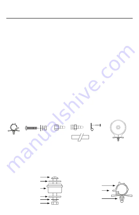
(Fig. 1) 150C-IG Compressor Installation Parts List: 


A.  Hose Bracket (1pc)

B.  Mounting Bolts (4pcs)

C.  Flat Washers (8pcs)

D.  Locking Washer (4pcs)

E.  Nuts (4pcs)

F.  1/8” NPT F x 1/4” Barbed Fitting (1pc)

G.  1/8” NPT M x 1/4” Barbed Fitting (1pc)

H.  Air Line Clips (3pcs) 

I.  Screws (3pcs)

J.  Remote Inlet Air Filter with Filter Element (1pc)

K.  1/4” Airline

(Fig. 2) Compressor 

Mounting Hardware

B.  Mounting Bolt

C.  Flat Washer

D.  Locking Washer

E. Nut

K.  Vibration Isolator

USER MANUAL

150C-IG COMPRESSOR KIT

REDUCER

B

A

C D E

F

G

H

I

J

(Fig. 3) Leader Hose Bracket

A.  Hose Clamp

M.  Clamp Release Tab

N.  Self-Anchoring Pin

B

C

C

D

E

K

REDUCER

A
M

N

K

Summary of Contents for 150C-IG

Page 1: ......

Page 2: ... damage to the compressor and your vehicle Each air compressor has been carefully produced and packaged Before installation please familiarize yourself with Installation Parts List Fig 1 of this manual Guidelines for Selecting Mounting Location The selection of proper mounting location for your air compressor will help ensure a long and trouble free compressor service life Please note the followin...

Page 3: ...r pressure switch The use of a relay is recommended Refer to the Recommended wiring diagram in Fig 4 10 Make sure that your compressor setup is properly fused For appropriate fuse size refer to amp draw of compressor in the specifications section of this manual 11 Always locate fuse as close as possible to power source 12 Before connecting to power source re check to make sure that all connections...

Page 4: ... 5 To prevent discharge of your vehicle s battery and enhance performance keep the vehicle s engine running while using the compressor 6 Only operate compressor in well ventilated areas 7 The use of a relay is strongly recommended for installation of this compressor 40 Amp relay value or higher MAINTENANCE REPAIRS 1 Periodically check all electrical and fittings connections Clean and tighten as ne...

Page 5: ...t Magnetic Horsepower 1 4 Max Working Pressure 150 PSI Max Duty Cycle 72 F 100 PSI 25 Minutes On Off 72 F 100 PSI 15 min 45 min Max Restart Pressure 150 PSI Max Ambient Temperature 158 F Min Ambient Temperature 40 F Auto Reset Thermal Protection Yes Ingress Protection Rating IP67 Dimensions 6 89 L x 3 27 W x 4 97H Net Weight 4 1 Lbs USER MANUAL 150C IG COMPRESSOR KIT ...

Page 6: ...85 SERIES 200 PSI 100 100 200 PSI ABOUT COMPRESSOR DUTY CYCLE Duty cycle refers to the amount of time a compressor can beoperated in a given time period at 100 PSI and a standard ambient temperature of 72 F It is commonly expressed in percentage format Compressor on time on time off time Duty Cycle ONE HOUR DUTY CYCLE MINUTES ON 100 PSI 72 F MINUTES OFF 9 5 Min On 55 Min Off 10 6 Min On 54 Min Off...

Page 7: ...in tank more frequently 2 Move compressor to area with less humidity or use air line filter Compressor will not run 1 No power or power switch in OFF position 2 Blown fuse 3 Motor overheats 4 Faulty pressure switch 1 Make sure compressor switch is ON 2 Disconnect compressors from power source replace fuse Refer to Specifications section for correct fuse amperage 3 Let compressors cool off for abou...

Page 8: ...ed as to the accuracy or completeness of the Manual Users must be aware that updates and amendments will be made from time to time to the Manual It is the user s responsibility to determine whether there have been any such updates or amendments Neither VIAIR nor any of its directors officers employees or agents shall be liable in contract tort or in any other manner whatsoever to any person for an...

Reviews: