USER MANUAL
DUAL ONBOARD AIR SYSTEM
AIR TANK & PLUMBING
1 4
-
(See Figure 1)
Tank Fittings:
the air tank.
P/N 20011
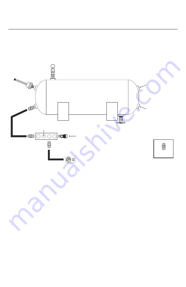
DUAL OBA PLUMBING DIAGRAM
Typical System Configuration, May Vary Depending on Installation
Tank
Drain
Cock
Safety
Valve
Pressure
Switch
Open Ports
Push-to-Connect
Straight Fitting
Quick Connect
Coupler
Coil Hose
Leader Hose
From Compressor #2
Leader Hose
From Compressor #1
5
0
0
35
15
10
1
20
25
30
2
**Wiring Harness NOT included
Plumbing Diagram:
(Figure 1)
Summary of Contents for 20075
Page 1: ......
Page 2: ...REDUCER REDUCER REDUCER R E D U C E R R E D U C E R ...


