Chapter 4 Chassis Web User Interface (UI)
Web UI Pages
Rev. D0
mA-1302/mA-1305 AXIe Chassis Operation Manual
May 2020
Page 4-13
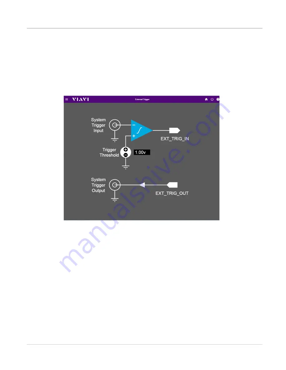
External Trigger Diagram
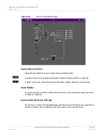
The External Trigger Diagram is accessed by selecting the "Click to Configure External
Trigger" block on the Triggers Page. The External Trigger Diagram is used to configure the
External Trigger Threshold.
“Configure External Trigger Source” on page 5-19
for information
about how to configure the Chassis to use an external signal as a trigger source.
Clock (Timing) Configuration Page
The Clock Configuration Page routes the signals used to establish Chassis timing. The
timing signals allow for synchronous or asynchronous timing of instrument modules within
a Chassis system. Available timing signals depend on the following:
•
Chassis timing defaults to the Chassis' Internal 10 MHz Frequency Reference
(INT_REF) if a selected external reference is invalid.
•
The Synchronous Recovered Ethernet Clock (SYNCE) is only available when the
Chassis Shelf Manager detects an Ethernet connection that supports synchronous
functionality.
•
10/100 MHz Frequency Reference (EXT_REF) is only available when the Chassis
Shelf Manager detects a valid External Frequency Reference.
Figure 4-7
Triggers - External Trigger Diagram
Summary of Contents for mA-1302
Page 1: ...mA 1302 mA 1305 AXIe Chassis Operation Manual ...
Page 3: ......


