background image

Chapter 4 Chassis Web User Interface (UI)

Web UI Pages

Rev. D0

mA-1302/mA-1305 AXIe Chassis Operation Manual

May 2020

Page 4-21

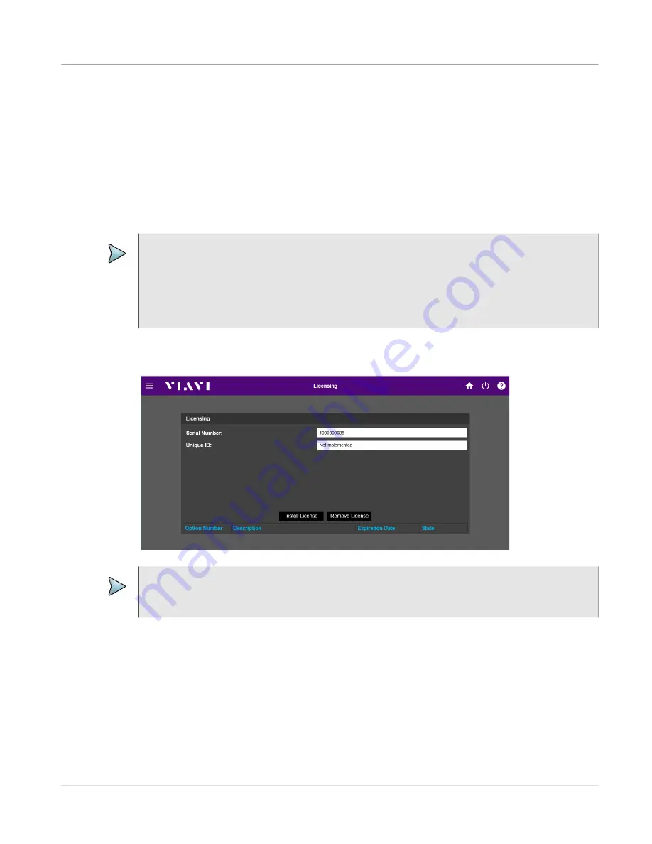
Licensing Page

The Chassis supports a variety of optional functions which are enabled by installing a 

software license in the Chassis System Module. The Licensing Page is used to install, 

update or remove Chassis option licenses.

When an option is purchased, an option license is generated for the product using the 

product's serial number and unique identifier (UID). The generated option license is 

distributed in a file named option.new. The option.new file must be installed in the Chassis 

in order to enable the optional function. 

NOTE

An option license can only be installed in the product for which the option was 

purchased. Attempts to install a license in a product other than the one for which the 

license file was issued generates a system error message.

The option.new file may contain multiple software licenses for different Chassis, or other 

CMP products (i.e., modules that are installed in the Chassis).

Figure 4-12

Chassis Licensing Page

NOTE

License Files are password protected to prevent users from accidentally removing 

option licenses; contact Customer Service to obtain the password.

Summary of Contents for mA-1302

Page 1: ...mA 1302 mA 1305 AXIe Chassis Operation Manual ...

Page 2: ...VIAVI Solutions 1 844 GO VIAVI www viavisolutions com mA 1302 mA 1305 AXIe Chassis Operation Manual Rev D0 ...

Page 3: ......
Page 4: ...ts This publication is independent of National Instruments which is not affiliated with the publisher or the author and does not authorize sponsor endorse or otherwise approve this publication PCIe and PCI Express are registered trademarks of the PCI SIG PXI is a registered trademark of the PXI Systems Alliance Copyright Release Reproduction and distribution of this guide is authorized for US Gove...

Page 5: ...om excessive exposure to chemicals known to the state to cause cancer birth defects or other reproductive harm The state maintains a list of such chemicals Businesses are required to provide a clear and reasonable warning before knowingly and intentionally exposing individuals in the state of California to a listed chemical A warning is not required if the anticipated exposure level will not pose ...

Page 6: ...mA 1305 Controls and Connectors Front Panel Controls and Connectors 2 2 Chassis Ground Connector 1 2 2 Chassis Instrument Slots 2 2 2 Chassis System Module 3 2 3 Power On Standby Button 4 2 3 Rear Panel Controls and Connectors 2 4 AC Power Input Connector 1 2 4 Fuse Holder 2 2 5 GNSS ANT Connector 3 2 5 PCIe Connector 4 2 5 Ethernet Connector 5 2 6 USB Connector 6 2 6 MultiShelf I O Connector 7 2 ...

Page 7: ...ation 3 6 Rack Mount Installation 3 7 Module Installation 3 8 Remove Filler Module 3 9 Install Module 3 9 Remove Module 3 11 Connect External Host Controller to Chassis 3 12 Desktop PCIe Connection Procedure 3 12 Laptop PCIe Connection Procedure 3 13 Wired LAN Connection Procedure 3 13 Installing Software 3 14 Chapter 4 Chassis Web User Interface UI Introduction 4 2 Recommended Web Browsers 4 2 Op...

Page 8: ... 5 19 Configure External Trigger Source 5 19 Configure Clock References 5 21 Internal Reference Timing Source 5 21 External Reference Timing Source 5 21 Use Chassis as a Timing Source 5 22 Use GPS as a Timing Source 5 22 Chassis Synchronization 5 23 Reference Clock for Chassis Synchronization 5 23 Sync Trigger Input for Chassis Synchronization 5 23 Chapter 6 Care and Maintenance Maintaining the Ch...

Page 9: ...ons Trigger Signal Definitions B 2 Clock Signal Definitions B 3 Synchronization Signal Definitions B 3 Appendix C PCIe Slot Configuration Procedure PCIe Domain Configuration Overview C 2 Viewing and Managing PCIe Domain Configuration C 2 PCIe Configuration Procedure C 4 System Hardware Configuration C 4 Prerequisites C 4 Appendix D External Host Controller Update Procedure Firmware Software Distri...

Page 10: ...2 Securing Latch Locked Position 3 10 Figure 3 3 Securing Latch Unlocked Position 3 10 Figure 3 4 Securing Latch Unlocked and unlatched 3 10 Figure 3 5 Computer with PCIe Connection 3 12 Figure 3 6 Laptop with PCIe Connection 3 13 Figure 4 1 Web UI Home Page 4 3 Figure 4 2 Web UI Home Page Components 4 4 Figure 4 3 Chassis Management Page 4 6 Figure 4 4 Instrument Slots Page 4 9 Figure 4 5 Trigger...

Page 11: ...Chassis Web UI Networking Page 5 15 Figure 5 8 Chassis Web Browser UI Homepage 5 16 Figure 5 9 Chassis Web Browser UI Networking 5 17 Figure 5 10 Chassis Web Browser UI Instrument Slot Navigation 5 18 Figure 5 11 Chassis Web Browser UI Instrument Slot Page 5 18 Figure 6 1 Auto Run Dialog Box 6 5 Figure 6 2 VIAVI Software Upgrade Tool Window 6 5 Figure 6 3 Chassis Self Test 6 7 Figure 6 4 Chassis S...

Page 12: ...pecifications A 2 Table A 3 mA 1305 Physical specifications A 2 Table A 4 Operating and storage environment A 2 Table A 5 Power supply A 3 Table A 6 Environmental Specifications A 3 Table A 7 EMC Compliance A 4 Table A 8 Safety Standards A 4 Table B 1 Trigger Signals B 2 Table B 2 Clock Signals B 3 Table B 3 Synchronization Signals B 3 ...

Page 13: ...List of Tables mA 1302 mA 1305 AXIe Chassis Operation Manual Rev D0 LOT ii May 2020 This page intentionally left blank ...

Page 14: ...sed include the following Purpose and Scope ii Intended Audience ii Related Information ii Terminology ii Contact Information iii Safety and Compliance Information iv Safety Hazards v Connecting to Power Supply viii Equipment Usage ix Case Cover Removal ix Electrostatic Discharge ESD x Ventilation Requirements x Electromagnetic Interference EMI xi ...

Page 15: ...ems and associated equipment and terminology Related Information This document and other Configurable Modular Platform CMP publications can be found on the VIAVI website at https www viavisolutions com en us products modular axie The following publication is referenced in this document mA 1302 mA 1305 AXIe Chassis Operation Manual 141171 Terminology The terms Chassis AXIe Chassis and device are te...

Page 16: ...iii Contact Information Contact Customer Service for technical support or with any questions regarding this or any other VIAVI products VIAVI Customer Service Department 10200 West York Street Wichita KS 67215 Telephone 800 835 2350 Fax 316 529 5330 email AvComm Service viavisolutions com ...

Page 17: ... is sensitive to Electrostatic Discharge ESD An item identified as ESD sensitive should only be handled by Qualified Service Personnel This symbol indicates the item meets the requirements of the applicable European Directives This symbol indicates a terminal may supply or be supplied with AC Voltage This symbol indicates Chassis Ground This symbol indicates a fuse location AC or DC Table 2 Safety...

Page 18: ... inhaled into the lungs can cause a respiratory disease In its solid form as used here it can be handled safely however avoid handling conditions which promote dust formation by surface abrasion Use care when removing and disposing of these components Do not put them in the general industrial or domestic waste or dispatch them by post They should be separately and securely packed and clearly ident...

Page 19: ...hipping Contact Customer Service for packaging and labeling instructions Mise en Garde Cet appareil contient une batterie au lithium et peut nécessiter un conditionnement spécial et un étiquetage externe lors de l expédition Communiquez avec le service à la clientèle pour les instructions d emballage et d étiquetage CAUTION Only use fuses specifically recommended for the device Refer to product Sa...

Page 20: ...ment être branché à une alimentation électrique CA mise à la terre WARNING The supply filter contains capacitors that may remain charged after the device is disconnected from the power supply The residual energy is within the approved safety requirements however a slight shock may be felt if the plug pins are touched immediately after removal Avertissement Le filtre d alimentation contient des con...

Page 21: ...lug containing an integral ground wire The ground wire must be securely fastened to ground grounding one terminal on a 2 terminal socket does not provide adequate protection Power Cord Requirements Use the AC Power Cord included with the Chassis to connect the Chassis to a grounded AC power supply If the AC Power Cord that was shipped with the Chassis is not available a replacement AC power cord t...

Page 22: ...ntation d accompagnement peut nuire au dispositif de protection de sécurité intégré dans l appareil CAUTION Do not operate this device with the case cover open Opening the case cover exposes the operator to electrical hazards which can result in electrical shock or damage to the device Mise en Garde N utilisez pas cet appareil avec le boîtier couvercle ouvert L ouverture du boîtier couvercle expos...

Page 23: ...ervice Personnel Mise en Garde Cet appareil est sensible aux DES et ils doivent seulement être installés enlevés ou entretenus par du personnel de service qualifié CAUTION Do not operate the Chassis with empty slots Install Filler modules in empty slots to ensure proper airflow through the Chassis Do not obstruct air flow to the air vents Do not place the Chassis on or close to other heat generati...

Page 24: ...ocate the receiving antenna Increase the separation between the equipment and receiver Connect the equipment into an outlet on a circuit different from that to which the receiver is connected Use properly shielded and grounded cables and connectors in order to meet FCC emission limits CAUTION Signal generators can be a source of Electromagnetic Interference EMI to communication receivers Some tran...

Page 25: ...About this Manual mA 1302 mA 1305 AXIe Chassis Operation Manual Rev D0 Preface xii May 2020 This page intentionally left blank ...

Page 26: ...A 1305 Overview This chapter provides a general description of the mA 1302 mA 1305 Topics discussed in this chapter include the following About the mA 1302 mA 1305 1 2 Principles of Operation 1 3 System Module 1 3 Power Entry Module PEM 1 3 Rear Transition Module RTM 1 3 Chassis Backplane 1 4 ...

Page 27: ...2020 About the mA 1302 mA 1305 The mA 1302 and mA 1305 AXIe Chassis are flexible development platforms that comply to AXIe 1 0 BaseArchitecture Specification Revision 3 0 The mA 1302 and mA 1305 can be used to create a wide range of test and development environments Figure 1 1 mA 1302 AXIe Chassis Figure 1 2 mA 1305 AXIe Chassis ...

Page 28: ...et switch fabric interface necessary for instrument slot communication and external user connectivity The System Module also provides Slot Timing and Chassis configuration and shelf management functions via the Web Browser User Interface Web UI Power Entry Module PEM The PEM contains a programmable micro controller that manages the Chassis main power supply and fan trays The PEM monitors for ON OF...

Page 29: ...Backplane provides two distinct starfabrics originating from the System Module and driven to all instrument slots The Chassis Backplane expands upon the AXIe 1 0 Base Architecture specification by providing three additional full fabric channels from the system slot fabric hub providing a total of sixteen transceiver lanes to each instrument slot The System Module utilizes these transceiver lanes f...

Page 30: ...MODULE A3 JTAG J17 J1 J2 AC POWER ENTRY FL1 FUSE XFL1 FUSE XFL2 XFL1 1 XFL1 2 XFL2 1 XFL2 2 BLU W3 BRN BRN GRN YEL BLU W4 CHASSIS GROUND W2 W5 N G L W7 P1 W1 P1 AC INPUT TACH PWMS 48V OUT JTAG W5 W6 W8 J1 J4 J3 J6 P1 P2 P1 SHELF MANAGEMENT J5 P2 POWER ENTRY MODULE A4A1 J48 JTAG J2 TEST PORT P1 P2 SYSTEM MODULE A5A2 SYSTEM MODULE 4U A5 P40 P41 P42 SLOT 1 SLOT 2 BACKPLANE A1A1 J102 J242 J232 J222 J2...

Page 31: ...Chapter 1 mA 1302 mA 1305 Overview mA 1302 mA 1305 AXIe Chassis Operation Manual Rev D0 Page 1 6 May 2020 This page intentionally left blank ...

Page 32: ... 2 Chassis System Module 3 2 3 Power On Standby Button 4 2 3 Rear Panel Controls and Connectors 2 4 AC Power Input Connector 1 2 4 Fuse Holder 2 2 5 GNSS ANT Connector 3 2 5 PCIe Connector 4 2 5 Ethernet Connector 5 2 6 USB Connector 6 2 6 MultiShelf I O Connector 7 2 6 Frequency Reference I O Connector 8 2 6 System Trigger Connector 9 2 7 WiFi ANT 10 2 7 NOTE Content does not include controls and...

Page 33: ...panel controls and connectors Chassis Ground Connector 1 The Chassis Ground Connector is used to connect an ESD wrist strap to the Chassis to provide ESD protection Chassis Instrument Slots 2 The mA 1302 contains two interchangeable instrument slots that accept AXIe modules the mA 1305 contains five interchangeable instrument slots Figure 2 1 mA 1302 Front Panel Controls and Connectors Figure 2 2 ...

Page 34: ...led Powering the Chassis on page 5 3 for additional information The On Standby Button has an LED Status Indicator that changes color to indicate operational status of the Chassis OFF The Chassis is off and has been disconnected from an AC Power Supply the On Standby Button LED is not illuminated ON Mode The Chassis is powered on and ready for use the On Standby Button LED is a constant green The O...

Page 35: ...he AC Power Input Connector is used to connect the Chassis to a grounded AC Power Supply When the Chassis is connected to an AC Power Supply the Power Entry Module PEM receives continuous power Figure 2 3 mA 1302 Rear Panel Controls and Connectors Figure 2 4 mA 1305 Rear Panel Controls and Connectors 1 3 5 7 8 9 2 4 6 10 1 3 5 7 8 9 2 4 6 10 NOTE The Chassis should only be connected to a grounded ...

Page 36: ... that require high speed data transfers between the Chassis and External Host Controller Establishing a PCIe Connection between the Chassis and External Host Controller requires one of the following External Host Controller with an operating system capable of PCIe slot enumeration A computer fitted with a PCIe Adapter card and PCIe cable A Laptop fitted with a PCIe ExpressCard Adapter and PCIe Ada...

Page 37: ...ntation Frequency Reference I O Connector 8 The Frequency Reference Input Connector is used to connect the Chassis to an external frequency reference The Frequency Reference Output Connector allows the Chassis to be used as a frequency reference by another device The Chassis Frequency Reference Input Output signals are routed and configured using the Chassis Web Browser User Interface Configure Cl...

Page 38: ...tem Trigger Input Output signals are routed and configured using one of the Chassis Web Browser User Interface See the following sections for information Configure Chassis Triggers 5 19 Triggers and Timing Configuration Pages 4 10 WiFi ANT 10 The WiFi Antenna is available to establish a wireless connection to the Chassis when a LAN connection is not available A WiFi Connection is sufficient to per...

Page 39: ...Chapter 2 mA 1302 mA 1305 Controls and Connectors Rear Panel Controls and Connectors mA 1302 mA 1305 AXIe Chassis Operation Manual Rev D0 Page 2 8 April 2020 This page intentionally left blank ...

Page 40: ...ller 3 3 Upon Receipt 3 4 Unpack the Chassis 3 4 Inspect Equipment 3 4 Verify Contents 3 4 Setting up the Hardware 3 5 Procedure Overview 3 5 Chassis Operation Verification Procedure 3 6 Chassis Work Environment 3 6 Bench Top Installation 3 6 Rack Mount Installation 3 7 Module Installation 3 8 Remove Filler Module 3 9 Install Module 3 9 Remove Module 3 11 Connect External Host Controller to Chassi...

Page 41: ... in the Chassis prior to shipment If an Embedded Host Module is being installed in the Chassis after the Chassis has been shipped from the factory refer to the documentation included with the module or refer to the section in this manual titled Module Installation on page 3 8 for instructions NOTE The Chassis ships from the factory with an assigned Static IP Address Do not connect the Chassis to y...

Page 42: ...ler used and the connection speed required PCIe Connection A PCIe Connection between the Chassis and External Host Controller is recommended for tasks that require high speed data transfers between the Chassis and External Host Controller Establishing a PCIe Connection between the Chassis and External Host Controller requires one of the following External Host Controller with an operating system c...

Page 43: ... 3 Remove Chassis from bottom packing mold 4 Remove Chassis from protective ESD packaging 5 Store packing material and shipping container for possible future use Inspect Equipment Inspect the Device for possible damage incurred during shipment Report any damage to VIAVI Customer Service Verify Contents Refer to packing list to verify shipment is complete Report any discrepancies to VIAVI Customer ...

Page 44: ...ived from the factory complete the procedures in the following sections to verify shipment and Chassis operation Upon Receipt Initial Setup Procedure Chassis Verify Chassis Operation Step 2 Install Chassis in Work Environment The Chassis is designed for bench top or rack mount use Refer to the following sections for Chassis installation instructions Bench Top Use Rack Mount Use Step 3 Install Modu...

Page 45: ...ssis setup and installation 2 Complete power on procedure 3 Complete Chassis Self Test Procedure refer to Self Test Procedure Chassis Work Environment The Chassis can be fitted for use on a work bench or in a rack environment Refer to the product Electrical Specifications on page A 3 for operating environment conditions Bench Top Installation When used as a free standing unit the Chassis should be...

Page 46: ...nt Kit The Rack Mount Kit Installation Guide is included with the Rack Mount Kit 4 Install the Chassis in the equipment rack per the Rack Mount Kit Installation Guide CAUTION The Chassis must be fitted with a Rack Mount Kit to properly install the Chassis in a test equipment rack Failure to use the approved rack mount accessories may result in damage to the Chassis Mise en Garde Le châssis doit êt...

Page 47: ...is section Refer to the Module s user documentation for safety installation and operating information CAUTION Modules are ESD sensitive and should only be installed removed and or serviced by Qualified Service Personnel Mise en Garde Les modules sont sensibles aux DES et ils doivent seulement être installés enlevés ou entretenus par du personnel de service qualifié CAUTION Modules are not hot swap...

Page 48: ...t or damaged CAUTION Do not operate the Chassis with empty slots Install Filler modules in empty slots to ensure proper airflow through the Chassis Mise en Garde N utilisez pas le châssis avec des fentes vides Installez des modules de remplissage dans les fentes vides afin d assurer un écoulement d air adéquat dans le châssis NOTE Some modules require specific hardware configurations and connectio...

Page 49: ...kplane Assembly Connectors 5 Press the securing latches into the Locked Position 6 Hand tighten the captive screw on each side of module Securely tighten each captive screw to ensure module is properly grounded via the Chassis NOTE The securing latch must be placed in the unlocked position pulled out and away from the latch mechanism or module cannot be properly inserted and seated with the Chassi...

Page 50: ...emove the module from the Chassis CAUTION Modules are ESD sensitive and should only be installed removed and or serviced by Qualified Service Personnel Mise en Garde Les modules sont sensibles aux DES et ils doivent seulement être installés enlevés ou entretenus par du personnel de service qualifié CAUTION Do not operate the Chassis with empty slots Install Filler modules in empty slots to ensure ...

Page 51: ...e Connection Procedure This procedure describes how to connect the Chassis to a Desktop Computer via a PCIe connection How to Establish Desktop PCIe Connection 1 Power down the Chassis to Standby Mode 2 Install the PCIe Adapter in the computer 3 Connect one end of the PCIe Cable to the PCIe Adapter Card 4 Connect the other end of the PCIe Cable to the Chassis PCIe Connector 5 Power on the Chassis ...

Page 52: ... Chassis Wait while the Chassis completes power up process 6 Power on the laptop 7 Access the Chassis UI via one of the Chassis Software UI Options Wired LAN Connection Procedure This procedure describes how to connect the Chassis to a computer or laptop via a Wired LAN connection How to Establish LAN Connection 1 Connect one end of an Ethernet Cable to the laptop or desktop computer 2 Connect the...

Page 53: ...rivers pre loaded on the Embedded System Module Regular checks should be performed to ensure that the Chassis and any installed AXIe Modules contain the most current firmware software and or drivers whichever is applicable Contact VIAVI Customer Service to check for the latest version of software firmware and or drivers See Software Firmware Updates on page 6 3 for information about updating syste...

Page 54: ...he Chassis Web Browser UI Introduction 4 2 Recommended Web Browsers 4 2 Open the Chassis Web UI 4 3 Web UI Layout 4 4 Header 1 4 4 Instrument Slot Buttons 2 4 5 Chassis Information Table 3 4 5 Web UI Pages 4 6 Chassis Management Page 4 6 Instrument Slots Page 4 9 Triggers and Timing Configuration Pages 4 10 Chassis Networking Page 4 17 System Update Page 4 19 Licensing Page 4 21 Self Test Page 4 2...

Page 55: ... like pressing the touchscreen swiping pinching to zoom in and pushing to zoom out desktop devices are controlled using a mouse and keyboard The Web UI layout auto adjusts to portrait or landscape layout according to the width of the web browser window and to the device on which the Web UI is being viewed i e desktop computer laptop computer or tablet Examples shown throughout this documentation i...

Page 56: ...Chassis IP Address in the browser s URL window 4 The AXIe Chassis Web Browser UI opens to the Home Page NOTE If using a viewing application to manage your AXIe system refer to the documentation provided with the application for instructions for accessing the AXIe Chassis Web Browser UI NOTE For first time use enter the Chassis default url which is http 10 105 8 32 Before connecting the Chassis to ...

Page 57: ...he Web UI The Header contains the following Main Menu Button The Main Menu Button opens and closes the Chassis Configuration Panel The Chassis Configuration Panel contains buttons which access CMP system data and Chassis configuration pages Power Options Button Selecting the Power Options Button displays a prompt which gives the user the option to restart the Chassis cycle Chassis power or turn th...

Page 58: ...nt Slot Buttons represent a real time view of the modules installed in the Chassis When the Chassis is powered on the Shelf Manager performs a standardized discovery routine which locates the modules that are installed in the Chassis The Shelf Manager identifies each module and updates the label on the Instrument Slot Button to identify the module Selecting an Instrument Slot Button opens the Inst...

Page 59: ...utine which locates the modules that are installed in the Chassis The Shelf Manager identifies each module s manufacturer information as well as each module s power cooling and backplane interface requirements The Shelf Manager then populates Web UI pages with the information gathered during the discovery process Chassis Management Page The Chassis Management Page contains data for the Chassis Bac...

Page 60: ...s empty Selecting a sensor button populates the Sensor Information section of the SubSystem Data Table SubSystem Sensor Information The SubSystem Sensor Information section of the SubSystem Data Table is populated when a Sensor Button is selected The type of sensor information displayed in the SubSystem Data Table depends on the SubSystem selected PCIe Domains Configuration The PCIe Domains Config...

Page 61: ...ectronic Keying is an extension of the AdvancedTCA E Keying process by which the Shelf Manager uses IPMI commands to enable disable the AXIe Backplane interface ports to ensure fabric channel compatibility and to prevent damage and or malfunction of boards AXIe E Keying information also includes shelf and module FRU information which describes the point to point connectivity of the AXIe timing and...

Page 62: ...ollowing module information Module Identification Module Sensors Module Status Module Sensor Readings Module Data Table Module Data Table is populated by selecting a module button on the Instrument Slots Page When a module button is selected the Module Data Table is populated with information for the selected module Module data includes information such as the manufacturer s name module descriptio...

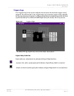
Page 63: ... Table is populated when a Sensor Button is selected The type of sensor information displayed in the Module Data Table depends on the module Triggers and Timing Configuration Pages The Chassis provides several trigger and timing signals which allow the Chassis to be configured to support a variety of test and measurement configurations The available trigger and timing signals allow for synchronous...

Page 64: ... selected group of signals The trigger signals that are available depend on the input signals detected by the Chassis Shelf Manager during the bootup discovery process Signal Relay Switches Signal paths are activated and de activated at Signal Relay Switches A purple circle with a purple signal path indicates a Signal Relay Switch is selected A black circle with a white signal path indicates a Sig...

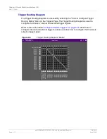
Page 65: ...e Click to Configure Trigger Routing Matrix block on the Triggers Page The Trigger Routing Diagram is used to configure the Chassis internal and external trigger signals Refer to the section titled Configure Chassis Triggers on page 5 19 about how to configure internal and external trigger sources as well as how to configure the Chassis to output a trigger signal Figure 4 6 Trigger Routing Diagram...

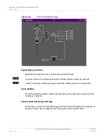
Page 66: ...ing Configuration Page The Clock Configuration Page routes the signals used to establish Chassis timing The timing signals allow for synchronous or asynchronous timing of instrument modules within a Chassis system Available timing signals depend on the following Chassis timing defaults to the Chassis Internal 10 MHz Frequency Reference INT_REF if a selected external reference is invalid The Synchr...

Page 67: ...th indicates a Relay Switch is selected A black circle with a white signal path indicates a Relay Switch is not selected Clock Divider The Clock Divider selection defines the frequency of the reference output as either 10 MHz or 100 MHz Stored Clock Reference Settings The manner in which the Shelf Manager sets the Chassis Timing Source depends on how the Chassis was configured when the system was ...

Page 68: ...the system was powered down the Shelf Manager will search for a valid external frequency reference If the Shelf Manager detects a valid external frequency reference at the Chassis External Reference Input Connector the Shelf Manager selects the External Frequency Reference as the Chassis timing source If the Shelf Manager does not detect a valid external frequency reference at the Chassis External...

Page 69: ...he Chassis clock reference Signal Relay Switches Signal Relay Switches route a signal along a desired path A purple circle with a purple signal path indicates a Relay Switch is selected A black circle with a white signal path indicates a Relay Switch is not selected Polarity Select The Polarity selection inverts the polarity of the selected Sync Signal NOTE MultiShelf I O Paths are reserved for fu...

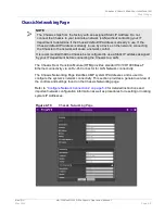
Page 70: ...ure Network Connections on page 5 9 for detailed instructions and important network configuration information as well as procedures for resetting or locating system IP Addresses NOTE The Chassis ships from the factory with an assigned Static IP Address Do not connect the Chassis to your local area network LAN without contacting your IT department to determine if the Chassis default IP Address is a...

Page 71: ...e Chassis Netmask When operating in DHCP Network Mode the Netmask field is a read only field that displays the network assigned Netmask When operating in Static IP Network Mode the Netmask field is used to assign a user defined Netmask to the Chassis Gateway When operating in DHCP Network Mode the Gateway field is a read only field that displays the network assigned Gateway Address When operating ...

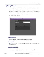
Page 72: ...splays and accesses the following information or functions View current version of Chassis firmware Check for available Chassis firmware updates Update Chassis firmware Installed Version Identifies the current version of firmware installed in the Chassis Update Mode The Update Mode drop down menu allows the user to select the mode that will be used to download firmware Repository IP Address This f...

Page 73: ...the Update Button initiates the firmware update Update Status The Update Status box displays status information and update progress of a firmware update The status of a firmware update is indicated by a percentage complete progress indicator bar NOTE The Check for Updates process only checks for new versions of Chassis firmware the process does not check the status of firmware software and or driv...

Page 74: ...n license is distributed in a file named option new The option new file must be installed in the Chassis in order to enable the optional function NOTE An option license can only be installed in the product for which the option was purchased Attempts to install a license in a product other than the one for which the license file was issued generates a system error message The option new file may co...

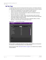
Page 75: ...ference and verifies the internal frequency reference is within tolerance Checks for the presence of trigger signal and verifies signal is within threshold Checks for the presence of a host controller module and verifies module temperature and voltage readings are within tolerance Verifies communication and data exchange when applicable between Chassis Backplane Chassis Modules and Chassis data I ...

Page 76: ...he Abort Button will stops the series of Self Test procedures as soon as the test that is in process is completed Select All Button The Select All Button enables all Self Test procedures Use case to select all but one or two test procedures by enabling all procedures then deselecting the one or two test procedures that you do not wish to run then press the Run Selected Button Deselect All Button T...

Page 77: ...Chapter 4 Chassis Web User Interface UI Web UI Pages mA 1302 mA 1305 AXIe Chassis Operation Manual Rev D0 Page 4 24 April 2020 This page intentionally left blank ...

Page 78: ...ing the Chassis 5 5 View Temperature Data 5 5 Manage Fans 5 7 Configure Network Connections 5 9 Chassis Default Network Settings 5 10 Configuring Network Mode of Operation 5 10 Managing Chassis IP Address 5 13 Configure Chassis Triggers 5 19 Configure Internal Trigger Source 5 19 Configure External Trigger Source 5 19 Configure Clock References 5 21 Internal Reference Timing Source 5 21 External R...

Page 79: ...m Module supports a Web Browser User Interface Web UI which allows the user to monitor and control Chassis configuration Retrievable information includes Chassis manufacturing information model number serial number etc Chassis fabric configurations including Ethernet configuration and PCIe virtual switches and or ExpressFabric configuration shelf module information trigger bus control and routing ...

Page 80: ...ure 4 The Chassis On Standby Button LED stays green when the power up process is complete Power off the Chassis This procedure should be used to routinely power down the Chassis In the event the Chassis is in an unresponsive state perform a Forced Power Down How to turn off the Chassis 1 Press and release the Chassis Power On Standby Button to initiate the power down process The Chassis Power On S...

Page 81: ... forced shut down 1 Press and hold the Chassis On Standby Button for approximately 5 seconds Release the On Standby Button when the Chassis On Standby Button LED flashes amber 2 If the Chassis On Standby Button LED flashes red press the On Standby Button again 3 Wait while the Chassis completes the power down process 4 When the Chassis completes the power down process the On Standby Button LED tur...

Page 82: ...ing the Chassis using the Web Browser User Interface Refer to Chapter 4 Chassis Web User Interface UI for descriptions of the Web Browser pages and parameters View Temperature Data Chassis Subsystem Temperature Data Chassis Subsystem Temperature Data is accessed by selecting the Backplane Subsystem temperature sensor Access Main Menu Chassis Management SubSystem Button Backplane Figure 5 1 Chassis...

Page 83: ...ion Manual Rev D0 Page 5 6 April 2020 Chassis Module Temperature Data Chassis Module temperature data is accessed by selecting a Chassis Module temperature sensor on the Instrument Slots Page Access Main Menu Instrument Slot Module Module Temperature Sensor Figure 5 2 Chassis Module Example Temperature Data ...

Page 84: ...d to ensure the Chassis and Chassis Modules are operating within OEM temperature specifications Access Chassis Fan Data and Settings Chassis fans data and settings are accessed on the Power Entry Page Access Main Menu Chassis Management Chassis SubSystems Power Entry Fan Bank 1or Fan Bank 2 Fan Readings Fan Readings display the current speed at which the fan is turning in revolutions per minute RP...

Page 85: ...ting Overrides In the event the Shelf Manager determines the temperature reading of a module exceeds the manufacturer specification the Shelf Manager performs the following actions A message is sent to the PEM to increase fan speed overrides any manual settings The Shelf Manager continues to monitor the Sensor Data Reports received from the PEM and other system sensors When the module reaches an a...

Page 86: ...ame network mode of operation DHCP or Static The IP address of each module in a CMP System must be within range of the other modules in the system or the modules will not be able to communicate with each other In the event you lose IP system connectivity perform the Chassis IP reset procedure How to Reset the Chassis IP Address on page 5 15 to restore system communication Once you restore connecti...

Page 87: ...Chassis and instrument trays for DHCP or Static network mode of operation NOTE When Chassis Network Settings are restored to factory default settings any active network connections are terminated and must be re established using the factory default settings Network Configuration Statement All VIAVI modules in a CMP System must be configured to use the same network mode of operation DHCP or Static ...

Page 88: ...e Network Settings Table 7 Select the Apply button At user prompt select the Apply and Reboot button NOTE The Chassis IP Address is required to perform this procedure If you do not know the Chassis IP address refer to Locate Chassis and Module IP Addresses on page 5 13 Changing the Chassis IP terminates any active network connections network connections must be re established using the newly assig...

Page 89: ...IP Address for other modules 9 Select the Apply button At user prompt select the Apply and Reboot button NOTE In order for the Chassis and instrument trays that comprise a CMP system to communicate with each other the IP address assignments assigned to the Chassis and instrument trays must be in range of each other netmasks must agree gateways must match etc As such when setting the Chassis to a s...

Page 90: ...Instrument Modules Procedure 1 Power on the CMP System 2 Open a web browser window 3 Enter localhost into the web browser URL field This will display the Embedded Host Module Web Browser User Interface Web UI 4 Enter the Chassis IP address in the web browser URL field NOTE This procedure applies to a CMP Chassis that contains an mA 3011 AXIe Embedded Host Module If the system does NOT contain an m...

Page 91: ...eration Manual Rev D0 Page 5 14 April 2020 5 The Chassis Web UI Homepage will be displayed The Homepage should resemble the example shown in Figure 5 5 6 From the Chassis Homepage open the Main Menu and select the Chassis Networking button Figure 5 5 Chassis Web UI Homepage Figure 5 6 Chassis Web UI Navigation ...

Page 92: ...nknown Restore Chassis Default IP 1 Connect one end of an Ethernet cable to the host controller 2 Connect the other end of the Ethernet cable to one of the Ethernet connectors on the CMP System 3 Navigate to the host controller s network settings window record the host controller s network settings for use later in this procedure 4 Set the host controller s IP to the Chassis Recovery IP Address 16...

Page 93: ...ost controller 9 Enter the Chassis Default IP Address 10 105 8 32 in the browser URL field to open the Chassis Web Browser UI NOTE At this stage in the procedure the Chassis IP Address must be changed to a different IP Address If the IP Address is not changed when the Chassis is rebooted the system will revert to the last stored IP Address the IP Address to which the Chassis was set prior to start...

Page 94: ...the host controller s network settings to the values recorded earlier in this procedure 13 Power cycle reboot the Chassis to activate and store the new IP address 14 Navigate to the browser window on the Host Controller Enter the newly assigned Chassis IP address in the browser window URL field Figure 5 9 Chassis Web Browser UI Networking NOTE When the Chassis is rebooted the web browser connectio...

Page 95: ...ion Manual Rev D0 Page 5 18 April 2020 15 Select Instrument Slots from the menu to view the instruments that are available in the Chassis 16 Select an instrument to view the instrument s IP address Figure 5 10 Chassis Web Browser UI Instrument Slot Navigation Figure 5 11 Chassis Web Browser UI Instrument Slot Page ...

Page 96: ... page Access Main Menu Trigger Diagrams 2 Select the Click to Configure Trigger Routing Matrix box from the Trigger Diagrams page 3 Enable the Signal Relay Switch for the desired TRIGn 0 11 to the desired TRIGn 0 11 Configure External Trigger Source This procedure explains how to configure a Chassis to use an external signal as a trigger source How to Configure External Trigger Source 1 Connect a ...

Page 97: ...Chassis to output a signal to be used by other equipment as a trigger source How to Configure Chassis as Trigger Source 1 Connect coaxial cable to Chassis External Trigger Out Connector 2 Navigate to the Trigger Routing Matrix page Access Main Menu Trigger Diagrams 3 Select the Click to Configure Trigger Routing Matrix box from the Trigger Diagrams page 4 Enable the Signal Relay Switch for the des...

Page 98: ...t Output signal connections The Shelf Manager must detect a valid external frequency reference signal at the Chassis External Reference Input Connector in order to configure the Chassis to use an external reference as a timing source This procedure provides instructions to configure a Chassis to use an External Reference as a timing source How to Configure Internal Reference Timing Source 1 Connec...

Page 99: ... or 10 100 MHz EXT_REF 4 By design a portion of the Chassis reference Clock is routed to the Reference Output Connector 5 Configure the Clock Divider setting Use GPS as a Timing Source This procedure explains how to configure a Chassis to use the system s GNSS Input Connector as a timing source How to Configure GPS Timing Source 1 Connect a coaxial cable from a GNSS antenna to the Chassis GNSS Inp...

Page 100: ...b UI Access Main Menu Sync Diagram 3 Select the CLK100 Signal Relay Switch 4 Configure the Sync Clock Divider Sync Trigger Input for Chassis Synchronization This procedure provides instructions to configure a Chassis to use the Trigger Input Signal for system synchronization This procedure involves routing a signal from the Chassis Trigger Input Connector to the Chassis internal trigger How to Con...

Page 101: ...Chapter 5 mA 1302 mA 1305 Control and Operation Chassis Synchronization mA 1302 mA 1305 AXIe Chassis Operation Manual Rev D0 Page 5 24 April 2020 ...

Page 102: ...ver the following topics Maintaining the Chassis 6 2 Storing the Chassis 6 2 Visual Inspections 6 2 External Cleaning 6 3 Software Firmware Updates 6 3 Firmware Software Distribution Methods 6 3 Updating Chassis Firmware Software 6 4 Chassis Self Test 6 7 Shipping the Chassis 6 9 Return Material Authorization RMA 6 9 Tagging Equipment 6 9 Shipping Containers 6 9 Freight Costs 6 10 Packing Procedur...

Page 103: ...t Visual Inspections Visual inspections should be performed periodically depending on operating environment maintenance and use Ensure that AC Power Cord and supply connector are in good condition Examine the stability and condition of covers and handles Check the presence and condition of all warning labels and markings and supplied safety information CAUTION This Device does not contain user ser...

Page 104: ...ce drivers pre loaded on the Embedded System Module ESM Users should perform routine checks to determine if a newer version of Chassis firmware and or device drivers is available Contact VIAVI Customer Service to check for the latest version of software firmware and or drivers Firmware Software Distribution Methods Firmware and software update distribution methods vary based on the export classifi...

Page 105: ...rmine which modules have updates available The VIAVI Software Upgrade Tool is distributed as part of the update ISO image Preliminary Procedure If the ISO image has been received on a USB device or CD proceed to the Firmware Software Upgrade Procedure page 6 5 If the ISO image has been downloaded from a secured file exchange server the ISO image must be burned to a USB device or a CD NOTE The info...

Page 106: ...essage and select the Run button to proceed 3 After the upgrade is confirmed the software upgrade tool window is displayed Figure 6 2 USE OF USB to CD ROM DEVICE A Y cable or dual USB connectors is required to draw enough current to power the external CD ROM device Connect external CD ROM device to mA 3011 Embedded Host module via a Y Cable or cable with 2 USB connectors If using a high powered US...

Page 107: ...e from the Devices to Upgrade section of the window and press the Add Device button 6 Select the Install button to continue 7 Wait while the system performs a series of automated processes This will take several minutes 8 When the upgrade process is complete the user will be prompted to power cycle the system 9 Power cycle the Chassis to apply the new changes NOTE Double click on the IP Address of...

Page 108: ...is an automated process that evaluates the Chassis operational status Refer to the section titled Self Test Page on page 4 22 for details about the fields and settings located on the Self Test Page Self Test Procedure Run All Self Test Procedures 1 Open the Chassis Web Browser UI 2 Navigate to the Self Test Page 3 Press the Run All Button Figure 6 3 Chassis Self Test ...

Page 109: ...5 AXIe Chassis Operation Manual Rev D0 Page 6 8 April 2020 To run a specific self test procedure 1 Open the Chassis Web Browser UI 2 Navigate to the Self Test Page 3 Select the test s to be performed then press the Run Selected Button Figure 6 4 Chassis Self Test Complete ...

Page 110: ... Equipment All items shipped to VIAVI must be tagged with Owner s Identification and contact information Nature of service or repair needed Model Number and Serial Number Return Authorization RA Number Shipping Containers Devices must be repackaged in original shipping containers using VIAVI packing materials If original shipping containers and materials are not available contact VIAVI Customer Se...

Page 111: ...Device Packing Procedure How to Package Chassis 1 Contact Customer Service to obtain a Return Authorization number return address and for questions about proper packaging 2 Tag the device 3 Insert bottom packing mold in shipping container 4 Place top packing mold securely on top of Chassis 5 Seal shipping container with tape 6 Include Return Authorization number on the packaging label NOTE VIAVI i...

Page 112: ...ance specifications for the mA 1302 and mA 1305 These specifications apply to both models except as noted Refer to the mA 1302 mA 1305 AXIe Chassis Data Sheet located on the VIAVI Solutions website for complete product specifications Unit Specifications A 2 Electrical Specifications A 3 Environmental Specifications A 3 Regulatory and Compliance Standards A 4 ...

Page 113: ...able A 1 Rack Units Model Specification mA 1302 2U x 19 mA 1305 4U x 19 Table A 2 mA 1302 Physical specifications Parameter Specification Height 88 1 mm Width 432 mm Depth 436 mm Weight 10 5 kg Table A 3 mA 1305 Physical specifications Parameter Specification Height 177 mm Width 432 mm Depth 436 mm Weight 12 2 kg Table A 4 Operating and storage environment Parameter Specification Operating Tempera...

Page 114: ... to 240 VAC 50 60 Hz Power Consumption mA 1302 800 W max 200 W allocated to each of 2 slots mA 1305 1400 W max 200 W allocated to each of 5 slots Fuse Requirements Dual 15A 250 V Type F Table A 6 Environmental Specifications Parameter Specification Operating Temperature 0 C to 50 C Storage Temperature 40 C to 71 C Warm up Time 30 minutes Relative Humidity 95 up to 40 C non condensing Altitude 4600...

Page 115: ...l Rev D0 Page A 4 April 2020 Regulatory and Compliance Standards Table A 7 EMC Compliance European EMC Directive 2004 108 EC IEC EN 61326 1 AS NZS CISPR 11 IECS NNM 001 Table A 8 Safety Standards European Low Voltage Directive 2006 95 EC IEC EN 61010 1 2nd Edition Canada CSA C22 2 No 61010 1 04 USA UL Std No 61010 1 2nd Edition ...

Page 116: ...ge B 1 B Appendix BTiming and Trigger Sources Signal Definitions This appendices describes the trigger and timing signals that are available for single Chassis systems Trigger Signal Definitions B 2 Clock Signal Definitions B 3 Synchronization Signal Definitions B 3 ...

Page 117: ... System Trigger Output is a 3 3V LVCMOS signal driven from the Trigger Routing Matrix to the Chassis Trigger Output Connector TIMESTAMP_TRIG API Programmable trigger trigger is programmed via API to occur at specified time events TRIG 0 11 Bidirectional MLVDS MultiPoint Low Voltage Differential Signal trigger pairs that are shared between backplane instruments and the Trigger Routing Matrix STRIG ...

Page 118: ...se an external 10 MHz or 100 MHz reference signal as a reference clock input SYNCE Recovered Ethernet The Chassis Internal Frequency Reference may be frequency synchronized when connected to an appropriate IEEE 1588 802 1 or Sync E signal network 10 100 MHz REF_OUT The External Reference Output Connector can be switched between a 10 MHz or 100 MHz signal Table B 3 Synchronization Signals Trigger L...

Page 119: ...Appendix B Timing and Trigger Sources Signal Definitions Synchronization Signal Definitions mA 1302 mA 1305 AXIe Chassis Operation Manual Rev D0 Page B 4 April 2020 This page intentionally left blank ...

Page 120: ...Configuration C 2 PCIe Configuration Procedure C 4 System Hardware Configuration C 4 Prerequisites C 4 Procedure C 5 Terms The following terms are using in this appendices The term root device refers to a device such as the COM Express CPU on an mA 3011 Host Module The term Endpoint refers to an instrument module that is installed in a CMP Chassis For example the mA 6806 AXIe 6 GHz VST module or m...

Page 121: ...ng and Managing PCIe Domain Configuration Chassis PCIe domain assignments are viewed and managed on the Chassis Management page in the PCIe Domain panel Press the Advanced Config button to display PCIe Domain settings Figure C 2 shows an example of how the PCIe Domain Advanced Settings page will look The settings on this page allow users to specify one Root for each domain and assign multiple Endp...

Page 122: ...example Domain 1 is the Embedded System Module ESM Domain 0 is the CPU Carrier mA 3011 Embedded Host located in Slot 1 The CPU Carrier is the root device for the following Endpoints target hardware Tx Rx 30GHz mA 6A30 AXIe 6 GHz VST with 30 GHz Downconverter NVMe Storage mA 3A01 AXIe Mass Storage Module Figure C 2 Chassis Management PCIe Domain Slot Configuration Tables ...

Page 123: ...Ie Mass Storage Module Slot 3 and 5 mA 6806 AXIe 6 GHz VST Module Slot 2 and 4 mA 3011 AXIe Dual Embedded Host Module Slot 1 Contact VIAVI customer service if you need assistance with modifying this procedure for use on systems with different hardware configurations Prerequisites This procedure requires the following LAN connection Chassis IP Address NOTE Read this procedure in it s entirety befor...

Page 124: ...rence hardware slot locations 1 Power on the Chassis 2 Open a browser window 3 Enter the Chassis IP address in the browser URL field 4 Navigate to the Chassis Management page 5 Select Root menu Select Slot 1 location of the mA 3011 Dual Embedded Host 6 Select the Advanced Config Button 7 Go to the Saved Configuration section of the PCIe Domains page 8 Set the following Endpoint parameters for Doma...

Page 125: ... Domain 0 a Known Device Manual b Slot Slot 2 c Device 2 13 Press the Add Endpoint button 14 Set the following Endpoint parameters for Domain 1 a Known Device Manual b Slot Slot 4 c Device 2 15 Press the Add Endpoint button 16 Select the Apply Button At prompt select the Apply and Reboot button NOTE The system must be rebooted twice for the new settings to take effect The first reboot is initiated...

Page 126: ...te the mA 1302 mA 1305 AXIe Chassis when the Chassis is being controlled by an External Host Controller the Chassis does not contain a VIAVI CMP mA 3011 AXIe Embedded Host Module Read this procedure in its entirety before proceeding Firmware Software Distribution Methods D 2 Procedure Requirements D 2 Directory Update Procedure D 3 USB Device Update Procedure D 4 ...

Page 127: ...e updates are distributed as a tar gz file The tar gz file will be distributed to customers on a USB device or CD OR An email will be sent to the end user with a link to download the tar gz file from a secure file exchange server Procedure Requirements The Chassis IP Address is required to perform the update procedure If you do not know the Chassis IP Address refer to the section titled Locate Cha...

Page 128: ... Enter the Chassis IP Address in the web browser URL field to display the Chassis Web UI 4 Navigate to System Update Page of the Chassis Web UI Access Main Menu System Update 5 Change Update Mode to File Path 6 Update the file path to point to the External Host Controller directory that contains the tar gz file 7 Press the Check for Update Button Wait while the module shelf manager queries the sof...

Page 129: ...web browser on the External Host Controller 4 Enter the Chassis IP Address in the web browser URL field to display the Chassis Web UI 5 Navigate to System Update Page of the Chassis Web UI Access Main Menu System Update 6 Change Update Mode to File Path 7 Update the file path to point to the USB device 8 Press the Check for Update Button Wait while the module shelf manager queries the software sou...

Page 130: ... Platform D E DAC Digital to Analog Converter dB decibel DHCP Dynamic Host Configuration Protocol EMI Electromagnetic Interference ESD Electrostatic Discharge G I GB gigabyte GbE Gigabit Ethernet GHZ gigahertz ICM Instrument Carrier Module IF Intermediate Frequency IPMB Intelligent Platform Management Bus IMPC Intelligent Platform Management Controller IPMC ...

Page 131: ...scillator LVDS Low voltage Differential Signaling MHz megahertz P S PCIe Peripheral Component Interconnect Express PEM Power Entry Module RA Return Authorization RTM Rear Transition Module RF Radio Frequency SPI Serial Peripheral Interface SoC System on Chip ShMC Shelf Management Controller SYNCE Synchronous Recovered Ethernet Clocki T U UI User Interface ...

Page 132: ...AVI Solutions North America 1 844 GO VIAVI 1 844 468 4284 Latin America 52 55 5543 6644 EMEA 49 7121 862273 APAC 1 512 201 6534 All Other Regions viavisolutions com contacts 141171 Rev D0 May 2020 English ...

Reviews: