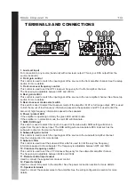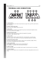
background image

4

MOUNTING GUIDELINES

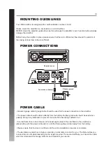
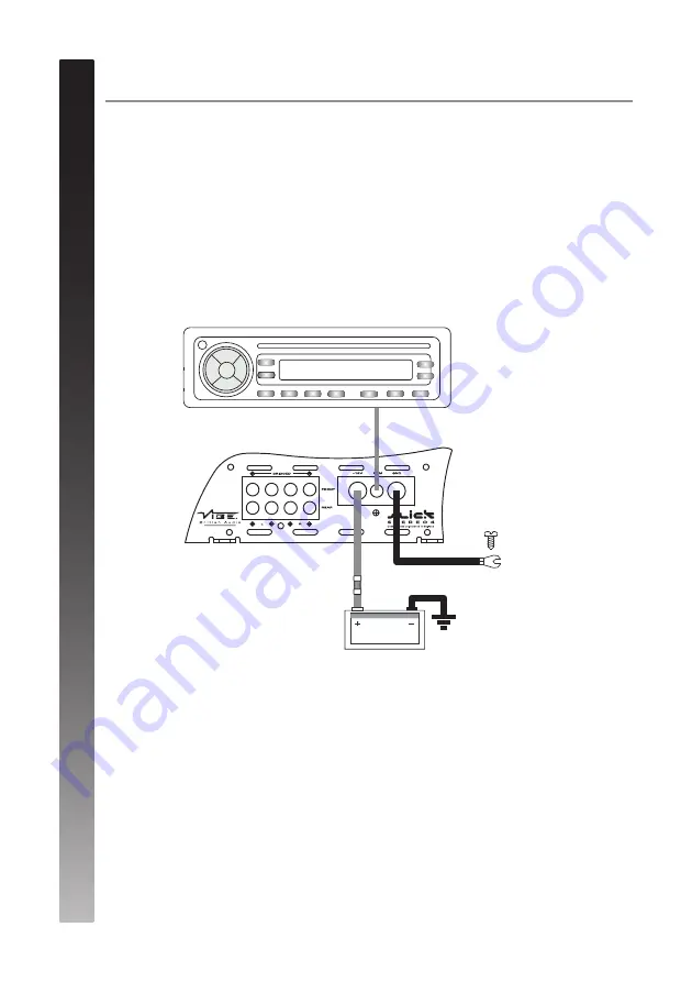
POWER CONNECTIONS

POWER CABLE

Your VIBE amplifi er is designed with a swift installation routine in mind. 

Please mount the amplifi er in a dry location on a solid surface. 
NEVER mount the amplifi er upside down as this will cause the amplifi er to over heat and will eventually 
damage the amplifi er. 

Before fi xing the amplifi er in place please ensure that there is suffi cient air fl ow around the exterior of 
the casing, at least two inches is suffi cient.

• At least 8 gauge cable 8 gauge cable should be used for the power connection to the amplifi er.

• The power cable should be taken directly from the battery. Rubber grommets should be used when
passing through any bulkheads to prevent the cable from becoming chaffed or cut.

• It is vital that a fuse / circuit breaker (of at least equal value to the one fi tted on the amplifi er) is
placed inline with the power cable and is no further than eighteen inches away from the battery.

• Please ensure that the fuse is not fi tted until the entire installation procedure is complete.

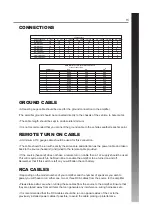
• The two tables overleaf are to help you decide on what cable is correct for you. The fi rst enables you 
to select the size of cable depending on the length required. The second will help you convert the cable 
size from American Wire Gauge to Metric and Imperial if you need to.

Chassis ground

Remote turn on

Fuse close to battery

Battery

Summary of Contents for Slick Bass 1

Page 1: ......

Page 2: ...ng system Most modern vehicles have sufficient capacity in the charging system as not all the electrical components of the vehicle will be switched on at once Check the fuse rating of the amplifier and use this as the peak current requirement Generally the continuous current draw will be a third of the peak current ATTENTION Durning the normal use of this amplifier the heatsink may become very hot...

Page 3: ...3 LIMITED WARRANTY ...

Page 4: ...ould be taken directly from the battery Rubber grommets should be used when passing through any bulkheads to prevent the cable from becoming chaffed or cut It is vital that a fuse circuit breaker of at least equal value to the one fitted on the amplifier is placed inline with the power cable and is no further than eighteen inches away from the battery Please ensure that the fuse is not fitted unti...

Page 5: ...ers you wish to power you will have to run either one two or three RCA cables from the source to the amplifier Please take extra care when running these cables from the source to the amplifier Ensure that they are placed away from all items that can generate any interference wiring harnesses etc It is recommended that the RCA cables should be run on opposite sides of the car to the previously inst...

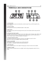
Page 6: ...the amout of low frequency information passed to the speakers and LPF is used to limit the amount of high frequency information passed to the speakers 5 Crossover frequency control This control is used to set the crossover frequency for the amplifier when HPF or LPF is selected The frequency is adjustable between 50Hz and 750Hz 6 Power protect LED If the amplifier is operating normally the green L...

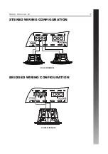
Page 7: ...STEREO WIRING CONFIGURATION BRIDGED WIRING CONFIGURATION 7 2 OHM MINIMUM 4 OHM MINIMUM Slick Stereo 2 ...

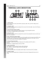
Page 8: ...de select switch This switch is used to select the crossover mode of the amplifier FLAT is full range output HPF is used to limit the amout of low frequency information passed to the speakers and LPF is used to limit the amount of high frequency information passed to the speakers 6 Crossover frequency control This control is used to set the crossover frequency for the amplifier when HPF or LPF is ...

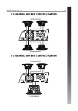
Page 9: ...9 Slick Stereo 4 4 CHANNEL WIRING CONFIGURATION 3 CHANNEL WIRING CONFIGURATION 2 OHM MINIMUM 2 OHM MINIMUM 2 OHM MINIMUM 4 OHM MINIMUM ...

Page 10: ...green LED will illuminate If the amplifier is in protection mode the red LED will illuminate 7 SUM SUB input This switch is used to select the input to be used for the subwoofer SUM setting will derive a signal from the rear channel input The SUB setting will use a separate RCA input such as the subwoofer output on the source headunit 8 Subwoofer gain control This control is used to match the inpu...

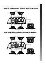
Page 11: ...11 Slick Channel 5 SINGLE SUBWOOFER WIRING CONFIGURATION DUAL SUBWOOFER WIRING CONFIGURATION 4 OHM MINIMUM 4 OHM MINIMUM 2 OHM MINIMUM 4 OHM MINIMUM 4 OHM MINIMUM 4 OHM MINIMUM 4 OHM MINIMUM ...

Page 12: ...his control is used to set the subsonic filter which is used to limit the very low frequency information passed to the subwoofer The frequency is adjustable between OFF and 50Hz 6 Crossover frequency control This control is used to set the LPF crossover frequency for the subwoofer amplifier channel The frequency is adjustable between 40Hz and 220Hz 7 Power protect LED If the amplifier is operating...

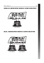
Page 13: ...13 Slick Bass 1 SINGLE SUBWOOFER WIRING CONFIGURATION DUAL SUBWOOFER WIRING CONFIGURATION 2 OHM MINIMUM 4 OHM MINIMUM 4 OHM MINIMUM ...

Page 14: ...round 60 120 Hz For a pair of full range speakers it is recommended that the crossover is set to Flat The two frequency controls will then have no effect on the amplifiers output and the speaker will receive a full range signal Using the high pass crossovers will allow more control of your speakers by removing the bass low frequencies The speakers can now perform at higher volumes with less distor...

Page 15: ...corded for training purposes MIDBASS Distribution PO Box 11000 B75 7WG Slick Stereo 2 Slick Stereo 4 Slick Bass 1 2 Channel 2 3 58mm 7 9 201mm 6 4 163mm 2 x 75 watts 2 x 100 watts 1 x 200 watts 4 x 75 watts 4 x 100 watts N A N A 2 x 200 watts 1 x 400 watts N A N A 1 x 600 watts 400 watts 800 watts 1200 watts 20Hz 20kHz 20Hz 20kHz 10Hz 500Hz 0 1 0 1 0 1 HPF LPF FLAT HPF LPF FLAT LPF Subsonic 50Hz 7...

Page 16: ......

Reviews: