background image

3303M11 

I

I

n

n

t

t

r

r

i

i

n

n

s

s

i

i

c

c

a

a

l

l

l

l

y

y


S

S

a

a

f

f

e

e


E

E

x

x

p

p

l

l

o

o

s

s

i

i

o

o

n

n

-

-

P

P

r

r

o

o

o

o

f

f


E

E

l

l

e

e

c

c

t

t

r

r

o

o

n

n

i

i

c

c


S

S

c

c

a

a

l

l

e

e


GZII-(B)CEx

 Series

Operation Manual

SHINKO DENSHI CO., LTD.


z

To ensure safe and proper use of the scale, please read this manual

carefully.

z

After reading this manual, store it in a safe place near the scale, so

you can review it as needed.

Instructions

Manual_GZ_V1

Summary of Contents for GZ II-12KCEx

Page 1: ...El le ec ct tr ro on ni ic c S Sc ca al le e GZII B CEx Series Operation Manual SHINKO DENSHI CO LTD z To ensure safe and proper use of the scale please read this manual carefully z After reading thi...

Page 2: ...s is operated shall be confirmed whether target gas suits the gas classification otherwise it will be dangerous for life and cause disaster like factory explosion by the gas ignition Any modification...

Page 3: ...between an intrinsically safe circuit and the frame of the electrical apparatus is not guaranteed Avoid excess voltage EC TYPE EXAMINATION CERTIFICATE Certificate No KEMA08ATEX0054 Marking STANDARS E...

Page 4: ...ale 11 5 Installation of the Power Supply Box 12 6 How to Replace Batteries 13 Basic Operation of the Scale 1 Getting Started and Checking Operation 14 3 Taring and Weighing 15 4 Notes on Handling the...

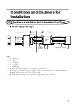
Page 5: ...g normal operation and even during a fault The E IS shall be an intrinsically safe explosion proof grounding pin for maintenance 14 13 GND DC20V 35V 10 11 12 1 2 3 4 5 6 GZD01 1 2 3 4 5 E IS 1 2 3 4 5...

Page 6: ...e stored in the battery box R14P from National Panasonic Connect 6 cells in series Battery replacement in a hazardous area is prohibited Hazardous area Metal connector Weight measurement circuit Weigh...

Page 7: ...x type is laid between the hazardous area and the non hazardous area Be sure to have the specified gas flow prevention work performed for the lead in section of the cable 3 Never set the power supply...

Page 8: ...iew GZ II B 2000CEx GZ II B 6000CEx to B 12KCEx GZ II B 30KCEx to 60KCEx Power supply box Provided for the power supply box type only Small sized scale 2 kg to 12 kg Medium sized scale 30kg to 60kg Di...

Page 9: ...on on page 17 Press this key to start or end the selection of a function Refer to Functions on page 26 and after Zero Taring key Press this key to zero a readout Refer to Taring and Weighing on page 1...

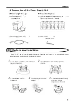
Page 10: ...e missing or broken please contact immediately the retailer of the scale or our Sales Office Small sized model Accessory Round pan base Square pan base Medium sized model Display Scale main body Pan b...

Page 11: ...n below may cause weighing errors or instrument failures 1 1 1 A loose floor on which the scale sinks when loaded with a sample 2 2 2 An unstable base or a location subjected to vibration 3 3 3 A loca...

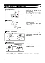
Page 12: ...e display Set the pan base with its screw hole aligned to the projection on the main body and tighten the screw with a screwdriver or an appropriate coin Attach the pan When a square pan is used a sub...

Page 13: ...the guide correctly the pole base cannot be installed on the scale Pass the scale cable under the pole from the wider side of the fitting hole Next attach the pole to the pole base Attach the display...

Page 14: ...Installation 10 Place the pan on the scale Attach the pan Pan...

Page 15: ...ntil the bubble in the level fits within the blue circle Press the four corners to check for rattling of each adjuster GZ II B 2000CEx to B 12KCEx GZ II B 30KCEx to B 60KCEx Level Adjuster Provided in...

Page 16: ...s area and the non hazardous area Be sure to extract the power cord from the wall socket before installing the power supply box Remove the acrylic cover and connect the power cable Connect the cable t...

Page 17: ...he cables Remove the battery box cover with the small wrench in the accessory kit Replace the batteries in the correct direction Install the cover with the small wrench Connect the relay connector of...

Page 18: ...zero is displayed in the weight display Push the pan slightly using your finger to check that the display readout changes Also check that zero is indicated in the display after the finger is released...

Page 19: ...T mark This mark disappears when another value is displayed 2 If approximately 1 5 of the weighing capacity is displayed as zero the mark that indicates that taring is ongoing is displayed At this tim...

Page 20: ...the scale is used after being stored for an extended period of time Refer to Calibration of the Scale on page 30 and after 5 5 5 Be sure to replace batteries in the non hazardous area The type of the...

Page 21: ...unction setting mode is assumed and the first item Function Selection is displayed For details refer to pages 26 and 27 Press the key and the rightmost value changes Then select the addition function...

Page 22: ...s the key so that zero is shown in the display When additional samples are placed in the container the weight of only the added samples is displayed g TOTAL 1 g TOTAL 3 g TOTAL 4 g g f TOTAL TOTAL 2 W...

Page 23: ...aded check beforehand that zero is displayed 2 When the addition operation is over press the key to clear the sum value This can prevent the sum by a new operation from being added to the preceding on...

Page 24: ...n memory and are not erased by power off The judgment result is indicated by HI OK or LO flagged with a e mark on the panel HI The measured value is greater than the upper limit value Upper limit valu...

Page 25: ...in and the setting process is terminated and the weight display mode is resumed 3 4 5 g 6 Select a condition Select a range to cover Select a setting type Setting is over Function Selection Select a c...

Page 26: ...ess the key and the upper limit value can be set is displayed temporarily and the judgment display HI is now flagged with the W mark Place the sample for the upper limit value on the scale and press t...

Page 27: ...ow They Work on pages 26 and 27 4 If all of the judgment displays HI OK and LO are flagged with the W mark the lower limit value is greater than the upper limit value Try the procedure again 5 You can...

Page 28: ...minus sign or Repeat the steps 3 and 4 Select the digit for value entry with the key and select a value to set with the key for entry of the lower limit value g W HI OK LO W g HI OK LO HI OK LO 1 HI...

Page 29: ...he set value is saved and is displayed Press the key again and the setting process is terminated and the weight display mode is resumed HI OK LO M HI OK LO g W 6 HI OK LO HI OK LO W g W 7 HI OK LO HI...

Page 30: ...Autopower off This function can be used only for the dry cell battery type ON Turns off the power automatically when approximately 3 minutes have elapsed Reserved Output is stopped 6 digit format Int...

Page 31: ...ms up to are displayed and then the next function is displayed Functional item Display Description Stop output Output continuously at all times 1 Output continuously if stable Stop output if unstable...

Page 32: ...yed each time the key is pressed For details refer to pages 26 and 27 Press the key and the setting is saved and is displayed Press the key again and the setting process is terminated and the weight d...

Page 33: ...es 26 and 27 Press the key and the rightmost value changes Then select the value that you want to set Press the key and the setting is saved and is displayed Press the key again and the setting proces...

Page 34: ...multaneously The display blinks and the zero point is calibrated When calibration of the zero point is completed the display changes automatically and the capacity point can now be calibrated Gently p...

Page 35: ...by using calibration weights whose total weight is at least half the weighing capacity 3 Be careful that you do not touch the pan and that the scale is not influenced by wind or vibration during adju...

Page 36: ...e correctly The displayed values changed after a long period of storage or when used in different locations 15P Redo the taring 11P Check to make sure the scale is level 30P Calibrate the scale Weighi...

Page 37: ...supply box type 230 VAC Dry cell battery type C size manganese dry cell battery R14P NR National Panasonic 6 10 Options Printer output For Shinko printers only RS232C D sub 25 pin RS422A D sub 25 pin...

Page 38: ...tion measuring section and pole The empty weight of the medium and large models is the sum of the weights of the display section and measuring section 2 2 Dry Cell Battery Type Type Model Weighing cap...

Page 39: ...HEAD OFFICE 3 9 11 YUSHIMA BUNKYO KU TOKYO 113 0034 JAPAN TEL 81 3 3835 4577 E MAIL shinko vibra co jp FAX 81 3 5181 6066 URL http www vibra co jp TSUKUBA PLANT 4219 71 TAKASAI SHIMOTSUMA IBARAKI 304...

Reviews: