background image

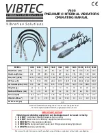
V600 

PNEUMATIC INTERNAL VIBRATORS 

OPERATING MANUAL   

We reserve the right to improve, modify or withdraw specifications or products without notice or obligation. 

MODEL 

V628 

V635 

V645 

V655 

V665 

V675 

V685 

V6105  V6140  V6160 

Head Diam. (mm) 

28 

35 

45 

55 

65 

75 

85 

105 

140 

160 

Head Length (mm) 

234 

278 

285 

316 

327 

366 

395 

395 

508 

508 

Frequency (VPM) 

18000 

18000 

17000 

17000 

18000 

18000 

17000  13500  10000  10000 

C/F Force (N) 

1440 

1924 

3500 

6050 

9301 

14851 

22184  22304  32460  49347 

Air Consumption (l/min) 

500 

608 

736 

820 

1018 

1218 

1600 

2100 

2880 

3750 

Weight (kgs) 

4.4 

10 

15 

19 

23 

35 

41.5 

Radius of Effectiv. (cm) 

16 

20 

25 

38 

44 

50 

55 

65 

95 

105 

S P Level (dB) 

104.5 

107.2 

113 

109 

113 

112.1 

109 

112.2 

115 

115 

Vibration (M.sec

2

3.2 

2.74 

4.5 

4.4 

2.24 

3.1 

4.4 

4.8 

4.8 

Air Pressure (psi) 

87 

Sound and Vibration readings taken 1 metre from the poker head 

Air Consumption established with supplied pressure of 6 bar 

IMPORTANT NOTICE


Vibrators and vibrating equipment can be dangerous if not used correctly. 

     1.  

DO NOT

 hold steel vibrating heads when running.  

     2.  

DO NOT 

stand or sit on vibratory equipment when running. 

     3.  

USE ONLY

 for the purpose intended. 

     4.  

USE ONLY

 when pneumatic hoses and fittings are securely tightened.   

     5.  

ALWAYS

 wear ear protectors.  


Summary of Contents for V628

Page 1: ...1600 2100 2880 3750 Weight kgs 4 4 6 8 9 10 15 19 23 35 41 5 Radius of Effectiv cm 16 20 25 38 44 50 55 65 95 105 S P Level dB 104 5 107 2 113 109 113 112 1 109 112 2 115 115 Vibration M sec2 3 2 3 2...

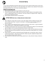
Page 2: ...t use the vibrator until it is re paired or replaced 5 The air supply must be switched off before any work is carried out on the vibrator To prevent accidental starting of the vibrator it must be disc...

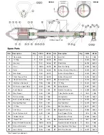
Page 3: ...xpose hose clip 10 Cut hose clip 10 to release inlet hose 11 from the handle Hold housing 4 in a vice and unscrew rear body 12 left hand thread removing complete with exhaust hose 15 If the hose is to...

Page 4: ...4 Models V 628 635 645 655 665 675 685 6105...

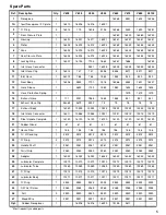
Page 5: ...76 76 17 Exhaust Body 1 16040 10225 10224 10223 10223 10222 10222 10222 18 Inlet Hose Connector 1 16311 10588 10588 10221 10221 10219 10219 10219 30 Steel Handle Complete 1 16120 16120 16120 16120 16...

Page 6: ...1 Lightly oil running faces of the rotor 2 Insert rotor so that the exhaust holes are in opposite end to the nosepiece 3 Fit a new O ring 2 onto the nosepiece 1 2 Removal of Rear Body Undo nut 36 and...

Page 7: ...pacer 1 1544 1544 Tube flexible handle 2 1555 1555 13 Nut rear body 1 1538 1538 Clamp Collar 2 16367 16367 14 Bush shock absorbing 1 1540 1540 Hex Head Screw 2 16373 16373 15 Sealing Ring Rear 1 1541...

Page 8: ...2 CHAPEL ROAD PORTSLADE BRIGHTON BN41 1PF ENGLAND Tel 44 0 1273 430977 Fax 44 0 1273 430978 Web www vibtec com E mail sales vibtec com...

Reviews: