3
General Maintenance
1. Vibrators are delivered without lubrication. Ensure to add oil before starting the vibrator.
2. Before connecting the vibrator, ensure the air line is clean from any water or dirt it may contain.
3. Refill lubricator after every four hours of use with 20/30 S.E.A. non-detergent oil.
4. To start the vibrator it may be necessary to tap the vibrator’s hardened nosepiece onto a firm surface.
5. After use, hang the vibrator with the head upwards and leave the control handle open to drain out of any
water or dirt.
Dismantling and Re-assembly Instructions
1. Replacement of Vane and Rotor
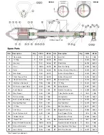
Hold housing (4) in a vice and unscrew nosepiece (1A) - right-hand thread. Remove from the vice and by
angling downwards the rotor is free to drop into the hand ensuring not to cause damage. The parts should
be cleaned and examined . If the nosepiece shows signs of excessive wear, then it should be replaced (see
point 4). Vanes must be a snug sliding fit in the rotor and fitted so that the vane cuts-out face away from the
milled slot in the rotor. Adjust length of vane to 0.1 - 0.15mm shorter than the rotor.
Re-assembly is opposite to the above, but the following should be observed:
1. Lightly oil running faces of the rotor.
2. Insert rotor so that the exhaust holes are in opposite end to the nosepiece.
3. Fit a new ‘O’ ring or fibre washer (2) onto the nosepiece (1A).
Note
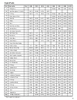
Some models (V665-V6105) have nosepieces (1) and separate front closure plates (3). Dismantling is similar
to the above and these two parts are available as spares.
2. Removal of Rear Body, Rear Closure Plate and Hoses
Cut exhaust hose clip (16), pull off exhaust hose (15) from exhaust body (17). Unscrew exhaust body (17)
from lubricator/handle (39/30), then pull out handle to expose hose clip (10). Cut hose clip (10) to release inlet
hose (11) from the handle. Hold housing (4) in a vice and unscrew rear body (12) - left-hand thread, removing
complete with exhaust hose (15). If the hose is to be replaced then unscrew hose sleeve (13), pull out hose
(15) from rear body (12) and remove hose protection spring (14) - only on models V675 - V6105. Using inlet
hose (11) pull out rear closure plate (7), locking ring (8) and inlet hose connector (9). All parts should be
cleaned and the rear closure plate (7) examined for signs of wear (see point 4).
3. Re-assembly
Rear closure plate (7), inlet hose fitting (9) and inlet hose (11) should be inserted into the housing as an as-
sembly, ensuring that the plate is kept square to the housing (4) and pushed onto the housing shoulder. Slide
new locking ring (8) over inlet hose (11) and locate behind rear closure plate (7). If necessary, fix exhaust
hose (15) into rear body (12), insert hose protection spring (14) - only models V675 - V6105, and clamp with
hose sleeve (13). The assembly can then be screwed onto the housing (4) ensuring that a new ‘O’ ring or
fibre washer (2) is fitted. Adjust hose lengths so that the inlet hose (11) protrudes approximately 65mm from
the exhaust hose (15). Slide new clips (10 & 16) onto respective hoses (11 & 15). Pass inlet hose (11)
through exhaust body (17) and fit onto inlet hose connector (18) using hose clip (10). Screw exhaust body
(17) onto control handle (30). Push exhaust hose (15) onto exhaust body (17) and fit hose clip (16).
4. Wear Criterion
The optimum condition of the vibrator turbine assembly to produce maximum speed and therefore power is
determined by the total air gap of the rotor. Ideally this should be between 0.06 - 0.13mm and a total gap
greater than 0.20mm greatly impairs the performance. The length of the rotor is 129.00 - 129.02mm when
assembled at the factory and if worn below 128.70mm, it should be replaced.
OPERATING AND MAINTENANCE INSTRUCTIONS
Models V 628, 635, 645, 655, 665, 675, 685 & 6105


