6
OPERATING AND MAINTENANCE INSTRUCTIONS
Models V6140 & V6160
General Maintenance
1. Vibrators are delivered without lubrication. Before using the vibrator ensure to add 20/30 S.E.A. non-
detergent oil.
2. Before connecting the vibrator, ensure the air line is clean from any water or dirt it may contain.
3. These models do not have any oil reservoir thus it is essential to use an air line lubricator.
4. To start the vibrator it may be necessary to tap the vibrator’s hardened nosepiece onto a firm surface.
5. After use, it is important that the vibrator is filled with 60ml of oil and run for 30sec. before storage.
Then hang the vibrator with the head upwards and the on/off valve open to drain out of any water or dirt.
Dismantling and Re-assembly Instructions
1. Replacement of Vane and Rotor
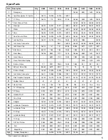
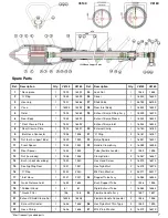
Hold housing (3) in a vice and unscrew nosepiece (1) - right-hand thread. Remove front plate (7) using 16mm
extractor. This allows the rotor (5) and vane (4) to be removed for inspection for wear and damage. Vanes
must be a snug sliding fit in the rotor and fitted so that the vane cuts-out face away from the milled slot in the
rotor. Adjust length of vane to 0.1 - 0.15mm shorter than the rotor.
Re-assembly is opposite to the above, but the following should be observed:
1. Lightly oil running faces of the rotor.
2. Insert rotor so that the exhaust holes are in opposite end to the nosepiece.
3. Fit a new ‘O’ ring (2) onto the nosepiece (1).
2. Removal of Rear Body
Undo nut (36) and remove handle (35), then undo nut (24) and clamp nut (21). You can then unscrew rear
body (6) - left hand thread. Should the rear plate (8) need to be removed, this can be pressed out. You will
need to remove the rotor first from the vibrator to do this.
Re-assembly is opposite to the above, but in order to refit the clamp nut (21), you will need to use M12
female extractor to slightly stretch the inlet hose (17) to line up the thread with the hole in the tube. Once
the clamp nut has been fitted, the rest of the handle can be assembled.
3. Removal of Bush
Hold handle tube (34) in a vice and unscrew nut (10) - right-hand thread. Unscrew locking nut (13) - left hand
thread, the tube will now separate from the rubber bush (14). To fit a new bush (14), replace the locking nut
(13) and push new bush into place. Then place tube with the new bush into the rear body (6) and refit nut (10).
4. Wear Criterion
The optimum condition of the vibrator turbine assembly to produce maximum speed and therefore power is
determined by the total air gap of the rotor. Ideally this should be between 0.06 - 0.13mm and a total gap
greater than 0.20mm greatly impairs the performance. The length of the rotor is 110.00mm when assembled
at the factory and if worn below 109.70mm, it should be replaced.

