background image

GENERAL

This manual is a guide to the installation and operation of
the V700 series fiber optic video transmission system.
Please read the entire manual before installing the equip-
ment.

NOTE: 

The series numbers  V700T and V700R are used

to describe all models of transmitters and receivers
unless noted otherwise.

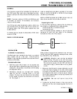
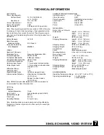
The V700 series video transmission system offers one-
way transmission of composite video from a camera to a
monitoring station. The V700 system operates over one
multimode fiber. 

A complete system consists of a transmitter, V700T, and a
receiver, V700R. 

Units are designed for standalone operation or for instal-
lation in Vicon’s V515R-PS or V517R-PS Card Cages
(V700T-R and V700R-R).

Both the V700T transmitter and V700R receiver have one
video input connector and one fiber connector.

Unpacking the Unit

In the event that anything is missing from the following
list, contact your authorized Vicon representative.

V700T Transmitter or V700R  Receiver
Instruction manual

Save the original packing materials in case it becomes
necessary to return the unit. Refer to the Shipping
Instructions at the end of this manual.

INSTALLATION

Installation Considerations

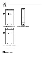
This fiber-optic link is supplied in two forms, as a stand-
alone module and as a rack card.  Units should be
installed in dry locations protected from extremes of tem-
perature and humidity.

Standalone Modules

1. Determine where the module is to be installed and

ensure that there is adequate space at both ends for
making the various cable connections and for reading
the diagnostic LEDs. 

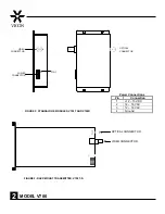
2. Standalone modules are provided with mounting

holes for four No. 6 screws (3-mm or 3.5-mm
screws). The type of screw chosen must be suitable
for the surface on which the module is to be mount-
ed.  See Figure 2.

Rack Cards

Rack cards are designed to be installed in one of Vicon’s
19-inch (483-mm) EIA standard card-cage racks, either
the V515R-PS or the V517R-PS. 

CAUTION:

Although a rack card may be installed

without turning off power to the rack (hot-swap-
pable), Vicon recommends that the power switch on
the rack power supply is turned OFF and that the
rack power supply is disconnected from any power
source.

1. Make sure that the card is oriented right-side up and

slide it into the card guides in the rack until the edge
connector at the back of the card seats in the corre-
sponding slot in the rack’s connector panel.  Seating
may require thumb pressure on the top and bottom of
the card’s front panel.

CAUTION:

Take care not to press on any of the

LEDs.

2. Tighten the two thumb screws on the card until the

front panel of the card is seated against the front of
the rack.

V700 SINGLE CHANNEL

VIDEO TRANSMISSION SYSTEM

continued on page 3

1

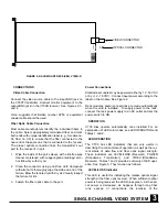
FIGURE 1: SYSTEM DIAGRAM

one

optical fiber

Video Out

Video In 

V700T

V700R

Summary of Contents for V700

Page 1: ...DUSTRIES INC 89 ARKAY DRIVE HAUPPAUGE NEW YORK 11788 TEL 631 952 CCTV 2288 FAX 631 951 CCTV 2288 TOLL FREE 800 645 9116 UK 44 0 1489 566300 WEB www vicon cctv com 24 Hour Technical Support 800 34 VICON 800 348 4266 Vicon part number 8009 8124 00 00 Section 10 Rev 0103 ...

Page 2: ...ideo systems and equipment for use in a wide variety of security safety control sur veillance and communication applications We stand behind the quality and dependability of every product with an industry leading Beneficial Use warranty If you are not satisfied with a Vicon product or service I would like to know Your complete satisfaction is the mission of every Vicon employee Sincerely Kenneth M...

Page 3: ...ironments 8 Accessories Do not place this video product on any unstable surface or table The video product may fall caus ing serious injury to a person and serious damage to the video product Use only with a mounting accessory recom mended by Vicon or sold with the video product Any mounting of the video product should follow Vicon s instruc tions and a mounting accessory recommended by Vicon shou...

Page 4: ...icing Do not attempt to service this video product yourself as opening or removing covers may expose you to dangerous voltage or other hazards Refer all servicing to qualified serv ice personnel 19 Damage Requiring Service Disconnect this video product from its power source and refer servicing to qualified service personnel under the following conditions Note that step c does not apply to outdoor ...

Page 5: ...d in dry locations protected from extremes of tem perature and humidity Standalone Modules 1 Determine where the module is to be installed and ensure that there is adequate space at both ends for making the various cable connections and for reading the diagnostic LEDs 2 Standalone modules are provided with mounting holes for four No 6 screws 3 mm or 3 5 mm screws The type of screw chosen must be s...

Page 6: ...E MODULES V700T AND V700R OPTICAL CONNECTOR VIDEO CONNECTOR POWER CONNECTOR PIN 1 Power Connections Pin Connection 1 12 16 VDC 2 12 16 VAC 3 12 16 VAC 4 Ground FIGURE 3 RACK MOUNT TRANSMITTER V700T R VIDEO CONNECTOR OPTICAL CONNECTOR ...

Page 7: ...the port Power Connections Standalone modules may be powered either by 12 16 VAC or by 12 16 VDC Connect input power according to the label on the module See Figure 2 Rack modules power connections are made automatically when the card is installed To supply power to the rack connect the rack power supply to an AC outlet and set the power switch to ON OPERATION V700 links operate automatically once...

Page 8: ...se of a problem cannot be determined con tact Vicon technical support at TOLL FREE 800 34 VICON 800 348 4266 or PHONE 631 952 CCTV 2288 SHIPPING INSTRUCTIONS Use the following procedure when returning a unit to the factory 1 Call or write Vicon for a Return Authorization R A at one of the locations listed below Record the name of the Vicon employee who issued the R A Vicon Industries Inc 89 Arkay ...

Page 9: ... Verify fiber connected within optical budget receiver power on Green Adequate video signal received from transmitter No action required VIDEO Red Inadequate video signal received from transmitter Check video input to transmitter and check LEVEL LOSS for optical signal strength LED Name Color Indicates Corrective Action Green Adequate input power applied to the module No action required POWER Off ...

Page 10: ...6 MODEL V700 FIGURE 5 DIAGNOSTIC LEDS LVL LOSS V700R R V700R R Rack Mount Receiver V700R Surface Mount Receiver LVL LOSS VIDEO V700T Surface Mount Transmitter POWER ...

Page 11: ...9 U coaxial cable Belden No 9259 or equivalent is recommended for video interconnection OPTICAL Maximum Optical Attenuation 13 dB Gain Control Fully automatic optical OAGC Optical Wavelength 850 nm Fiber Type 62 5 um Operating Distance 3 2 mi 5 2 km Note Operating distance is approximate and will be affected by the type and number of splices in the fiber and by the exact type of fiber used CONNECT...

Page 12: ...quarters Brunel Way Fareham PO15 5TX United Kingdom 44 0 1489 566300 Fax 44 0 1489 566322 Brussels Office Planet II Unit E Leuvensesteenweg 542 B 1930 Zaventem Belgium 322 712 8780 Fax 322 712 8781 Vicon China Unit 5 17 F Metropole Square 2 On Yiu Street Shatin New Territories Hong Kong 852 2145 7118 Fax 852 2145 7117 Internet Address www vicon cctv com ...

Reviews: