
028-5009-04_LIT-R851V-E06-EN
Sep-19
1
Innovative Control Solutions For Your Needs
R851V STEP CONTROLLER
WITH INTEGRATED VERNIER STAGE
•
Pulsed or analog 0 to 10 Vdc vernier stage
•
8 step models
•
Up to 16 stage total with a slave unit
•
Test button
DESCRIPTION
The Viconics R851V series step controller is designed for cost
effective, precise modulation of multi-stage control application. A
common application is a multi-step electric duct heater.
An integrated vernier control output will give a precise and full
modulation of the load from 0 to 100% of the total capacity.
FEATURES AND BENEFITS
Microcomputer-based design
Accuracy and reliability
Adjustable inter-stage delay
Provides flexibility in
replacement applications
Adjustable Vernier ratio
Simplifies design of
proportional stage
Choice of pulsed or analog
Vernier output
Permits use of SCR or lower
cost SSR
Up to 16 stages
One product family can handle
all applications
Choice of LIFO or FIFO
sequencing
Increased flexibility of FIFO
permits even use of contactors
Test button
Quick troubleshooting
MODELS AVAILABLE
The R851V is available in 1 model
•
R851V-8
8 stage unit
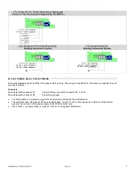
If more than 8 stages are required, the R851B-8 can be used as a
master unit with another R851V as a slave unit. Adding another unit
can bring the total step number up to 16.
SPECIFICATIONS
Operating conditions:
0°C to 80°C ( 32°F to 176°F )
0 % to 95 % R.H. non-condensing
Relay outputs:
Pilot duty:
-
24 - 120 Vac – 720 VA
-
240 Vac – 690 VA
Motor load:
-
120 Vac – 1 HP
-
240 Vac – 2 HP
Vernier stage: 0 to 10 Vdc, 5 mA max.
Vdc pulsed, 6 Vdc, 30 mA max.
Input impedance: 0 to 10 Vdc into 10 K
Ω
minimum
Power supply: 24 Vac -15%, +10% 50/60 Hz; up to18 VA
Use a Class 1 ( properly fused ) or Class 2, CSA or UL recognized
transformer for power supply & relay outputs.
Agency Approval: cULus File # E212649
Specifications and equipment are subject to change without prior notice.
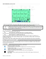
OVERRIDE TEST BUTTON
The override test button can be used to by-pass the interstage delay and
bring on all stage at one time. This simplifies the verification of configured
maximum number of stage. A status led per step will come on for each of
the configured stage.
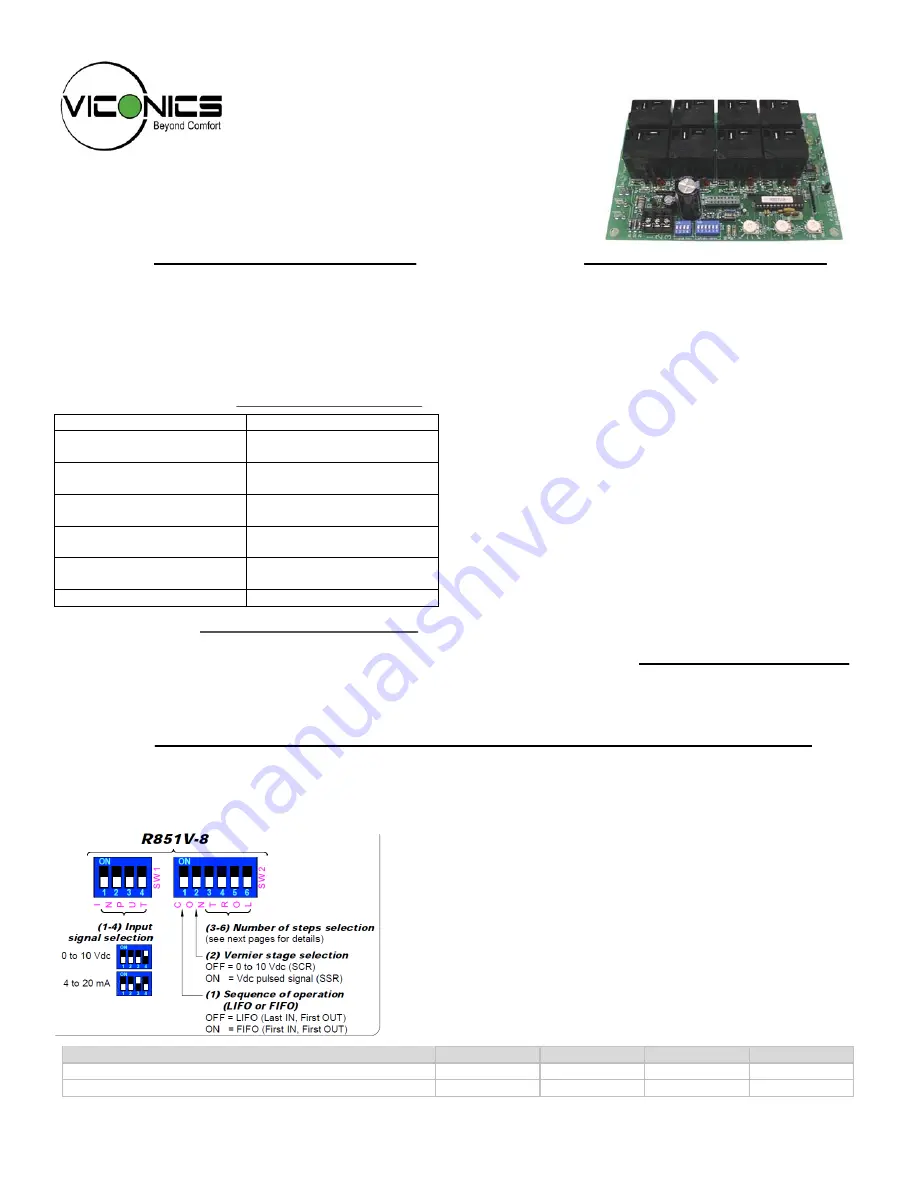
INPUT SIGNAL
The R851V has four
INPUT
dip switch
(S1 to S4)
to select the control signal input:
They are compatible with industry standard signals.
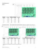
DIP SWITCH ADJUSTMENTS & WIRING CONTROL INPUT
Input Signal Switch
Switch #1
Switch #2
Switch #3
Switch #4
0 to 10 Vdc control signal ( 2 to 10 Vdc control range )
Off
Off
Off
On
4 to 20 mA control signal
Off
Off
On
Off
If a slave unit is used, wire the control signal input to the master unit only


