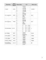
background image


27


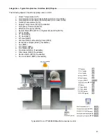
Integrating Viconics’ Devices on an MSTP Network   


Before doing any BACnet integration, make sure to have Viconics’ PICS (Protocol Implementation Conformance 
Statement).  
This PICS document lists all the BACnet Services and Object types supported by a device and can be found at 

www.viconics.com

.  


Viconics’ devices do not support the COV service. COV reporting allows an object to send out notices when its 
Present-Value property is incremented by a pre-defined value. Since this is not supported at Viconics’ end, special 
attention should be given to the polling time settings at the Supervisory Controller and Workstation level when 
using a graphic interface or an application program to read or write to a Viconics’ object. 


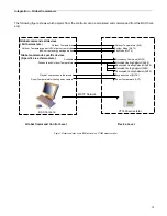
Graphical interfaces 

For example, some graphic interface might poll every data linked to the graphic page on a COV basis. If the 3

rd


party device does not support COV, the graphic interface then relies on a pre-configured polling interval, which is 
usually in hundredths of milliseconds. Any device containing a monitored object could be subject to network traffic 
congestion if such a polling interval is used. Viconics strongly recommend a polling interval of 5 seconds minimum 
for any graphic interface. This becomes even more critical in area graphics where a single representation might poll 
many devices. If proper poll rate is not respected, devices may be reported offline by certain front end by saturating 
the traffic handling capacity of BACnet MSTP without COV subscription. 


Free programmed object or loops 

As for the application program, you might want to read and write any MSTP data on an “If Once” basis or a “Do 
Every” loop basis instead of reading or writing to a 3

rd

 party device’s object directly in the program. Otherwise, any 

read or write request will occur at the Supervisory Controller’s program scan rate, which might as well be in 
hundredths of milliseconds. This can easily bog down a network as single commands can be sent to all ASC 
devices down the MSTP trunks every hundredth of milliseconds 
Programs writing to the devices should have a structure similar to the following: 


If Once Schedule = On then 
  MV11 = Occupied 
End If 
If Once Schedule = Off Then 
  MV11 = Unoccupied 
End If 


OR 
 

Do Every 5min 
 If Schedule = On Then 
   MV11= Occupied 
 Else 
    MV11 = Unoccupied 
 End If 
End Do 


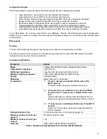
Retries and Timeouts 

Another thing to look for in a BACnet integration is the Device object of the Supervisory Controller (and the 
Operator’s Workstation). This object contains the 2 following required properties: 
1) Retry 

Timeout; 

2) 

Number of APDU Retries; 


1) The Retry Timeout property specifies the time between re-transmissions if the acknowledgement has not been 
received. When you are experiencing problems with controllers dropping off-line, increasing this value may help.  


2) The Number of APDU Retries property specifies the number of times unsuccessful transmissions will be 
repeated. If the receiving controller has not received the transmission successfully after this many attempts, no 
further attempts will be made. 


For example, if one of the controllers does not reply to a Supervisory Controller (SC) request, and the SC’s Retry 
Timeout is set to 2000 msec and the Number of APDU Retries is set to 1 (still at the SC level), then the SC will 
send one other request, 2 sec later. If the MSTP device does not reply, it will be considered Off-line by the 
workstation. 


So having a Retry Timeout value of 10000 msec and a Number of APDU Retries property set to 3 at the SC level 
may prevent device from dropping Off-line. These properties should also be changed at the Workstation level since 
the workstation will likely issue requests to any MSTP devices when the graphics are used. 

Summary of Contents for VT76 Series

Page 1: ...1 PIR Ready VT76xx Series With Without Scheduling Controllers For Commercial HVAC Applications BACnet Integration Manual ITG VT76xx PIR BAC E02 028 6015_R2 Issue Date January23 2011...

Page 2: ...r without a factory installed PIR cover Fig 1 VT7600 Series The additional following documentation is available on www viconics com Detailed information on the controller VT76xxX5x00x is available on...

Page 3: ...Application Specific Controller B ASC The BACnet controller series supports the following BACnet Interoperability Building Blocks BIBBs Application Service Designation Data Sharing Read Property B DS...

Page 4: ...ADPU Length Property 62 R Maximum ADPU Length accepted Default is 244 ADPU Timeout Property 10 R ADPU timeout value Default is60 000 ms Application Software Version Property 12 R Controller base appl...

Page 5: ...e R W Outdoor Temperature AV 9 Present_Value R W Outdoor Temp Override BV 10 Present_Value R W Room Humidity AV 11 Present_Value R W Room Humidity Override BV 13 Present_Value R W Occupancy Command MV...

Page 6: ...tput AV 22 Present_Value R Analog Heat Output AV 35 Present_Value R Controller Status GRP 23 Present_Value R AUX BI 24 Present_Value R G Fan BI 25 Present_Value R Y1 Cool BI 26 Present_Value R Y2 Cool...

Page 7: ...d Heat Setpoint AV 42 Present_Value R W Occupied Cool Setpoint AV 43 Present_Value R W Unoccupied Heat Setpoint AV 44 Present_Value R W Unoccupied Cool Setpoint AV 45 Present_Value R W Fresh Air Level...

Page 8: ...t_Value R W Power up Delay AV 60 Present_Value R W Temporary Occ Time MV 61 Present_Value R W Fan Control BV 62 Present_Value R W Anticycle MV 63 Present_Value R W Fan Purge Delay BV 64 Present_Value...

Page 9: ...r Changeover Setpoint AV 77 Present_Value R W Economizer Minimum Position AV 78 Present_Value R W Mechanical Cooling Enabled BV 79 Present_Value R W Mixed Air Setpoint AV 80 Present_Value R W Heatpump...

Page 10: ...Dehumidification Lockout Functions MV 92 Present_Value R W Dehumidification Output Status BI 93 Present_Value R Humidification Model Configuration Options GRP 94 Present_Value R AI1 Config BV 94 Prese...

Page 11: ...B VT7656B5x00B VT7607B5x00B VT7657B5x00B VT7600H5x00B VT7652H5x00B VT7600W5x00B VT7652W5x00B VT7606E5x00B VT7656E5x00B VT7600F5x00B VT7652F5x00B Minimum CO2 Level AV 100 Present_Value R W Humidifier O...

Page 12: ...chedule Weekly_schedule Present_Value Weekly_Schedule a The following AV s are defined as read only When Out_of_Service properties is set to true the Present_Value if written is not derived to the app...

Page 13: ...0 F 37 5 80 F 26 5 C Heating Setpoint Limit AV 48 40 F 4 5 C 90 F 32 C 90 F 32 C Cooling Setpoint Limit AV 49 54 F 12 C 100 F 37 5 54 F 12 C Heating Lockout Temperature AV 50 15 F 26 C 120 F 49 C 120...

Page 14: ...V 96 0 100 N A Supply Heat Lockout Temperature AV 96 15 F 26 C 120 F 49 C 32 F 0 C Humidification High Limit Spt Setpoint AV 97 50 90 85 Supply PI Heat Demand AV 97 0 100 N A Low RH Setpoint AV 98 10...

Page 15: ...Cool BI 27 Off On Off W1 Heat BI 28 Off On Off W2 Heat BI 29 Off On Off Reversing Valve BI 30 Off On Off DI 1 Status BI 31 Not Activated Activated Not Activated DI 2 Status BI 32 Not Activated Activat...

Page 16: ...79 Off On Off Comfort Mode BV 84 Comfort Economy Comfort High CO2 Alarm BI 84 Off On Off Reversing Valve Configuration BV 85 Normally Cool Energized in Heating Normally Heat Energized in Cooling Norma...

Page 17: ...2 Auto 3 Cool 4 Heat Fan Mode MV15 1 On Smart 2 Auto 3 Smart Keypad Lockout MV18 1 Level 0 Level 0 2 Level 1 3 Level 2 Effective Occupancy MV 34 1 Occupied Depends on local occupancy 2 Unoccupied 3 Te...

Page 18: ...None None 2 RemNSB 3 RemOVR 4 Filter 5 Service 6 Fan lock Proportional Band MV 67 1 2 2 F 0 6 C 2 2 3 3 F 1 2 C 3 4 4 F 1 7 C 4 5 5 F 2 2 C 5 6 6 F 2 8 C 6 7 7 F 3 3 C 7 8 8 F 3 9 C Event Display MV71...

Page 19: ...ode MV15 Occupied Heating Setpoint AV42 Unoccupied Heating Setpoint AV44 Occupied Cooling Setpoint AV43 Unoccupied Cooling Setpoint AV45 Restrict user access to thermostat Keypad Lockout MV18 Outdoor...

Page 20: ...fective Occupancy MV34 System Mode RTU MV14 or System Mode HPU MV13 G Fan BI25 Y1 Cool BI26 Y2 Cool BI27 W1 Heat BI28 W2 Heat BI29 or Reversing Valve BI30 Economizer Output AV22 if available Aux BI24...

Page 21: ...controllers For clarity we will use the term Device to represent any product with an active EIA 485 network connection including Viconics and non Viconics controllers Summary Specifications Parameter...

Page 22: ...ystems with long lengths benefit from using low capacitance cable i e 17pF ft or lower Network Configuration EIA 485 networks use a daisy chain configuration A daisy chain means that there is only one...

Page 23: ...Maximum Cable Length The maximum length of a chain is related to its transmission speed The longer the chain the slower the speed Using proper cable the maximum length of an EIA 485 daisy chain is 40...

Page 24: ...ate daisy chains branch from each repeater Do not install repeaters in series as this may result in network reliability problems Figure 6 demonstrates an incorrect use of a repeater in an EIA 485 netw...

Page 25: ...OL resistor value Network Adapter The polarity of the connection to the cable is important From one module to the other it is important that the same coloured wire be connected to plus or and the othe...

Page 26: ...ce of a network N A Right after power is applied 2 long blinks and then no blinking Polarity has been reversed at the module Reverse polarity at the module Table 2 Status LED condition and possible so...

Page 27: ...rogram Otherwise any read or write request will occur at the Supervisory Controller s program scan rate which might as well be in hundredths of milliseconds This can easily bog down a network as singl...

Page 28: ...the MS TP communication port is initialized on power up If the network speed is changed the device will keep listening at the previously detected speed for 10 minutes before resuming auto bauding Re...

Page 29: ...Do not exceed the maximum number of devices and maximum length allowed by the EIA 485 specifications Too many devices were installed without any repeaters Repeaters need to be installed as specified...

Reviews: