Parameter Description VD520 Series Inverter User Manual
- 108 -
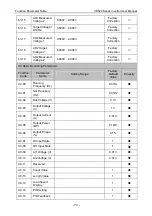
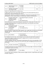
F1-15
Restart Selection Upon
Power Failure
0: Enabled
1: Disabled
0
○
F1-16
Waiting Time of Restart
Upon Power Failure
0.0s~60.0s
0.0s
○
Used to run command source is terminal control.
Enabled: when terminal run command has maintained, inverter will autostart after power on
self-inspection normal and delay the time of F1-16.
Disabled: when terminal run command has maintained, inverter will not autostart after power on
self-inspection normal, only start when run command given again after disconnecting.
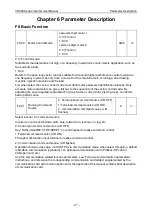
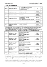
F1-17
Operation Mode of Set
Frequency is Lower
than the Frequency
Lower Limit
0: Running with frequency lower limit
1: Stop
2: Zero speed running
0
○
When set frequency is lower than the frequency lower limit, the running state of inverter can be
through the parameter selection. VD520 provide three kinds of running mode, meet various
application requirements.
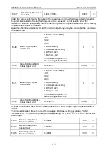
F1-18
Start Selection of Set
Frequency is Lower
than the Start
Frequency
0: Don’t start
1: Zero speed running
1
◎
When set frequency is lower than the start frequency, the running state of inverter can be through the
parameter selection. VD520 provide two kinds of running mode, meet various application
requirements.
F1-19
Run Direction
0: Same direction
1: Opposite direction
0
○
By changing the function code, can not change the motor wiring and implement the purpose of
change motor rotation, its effect is equivalent to adjust motor (U, V, W) any two lines for motor
direction of rotation transformation.
Tip: after initialization parameter will restore the original state of the motor running direction. For the
occasion that forbidden to change the motor rotation after system debugging good should be used
with caution.
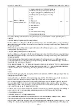
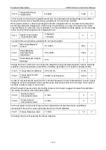
F1-20
Reverse Control Enable
0: Allow reverse
1: Prohibit reverse
0
○
Through the parameter set inverter is allowed to run or not in reverse state, in the case of not allow
motor reversal, need to set F1-20=1.
F1-21
FWD/REV Rotation
Dead-zone Time
0.0s~3000.0s
0.0s
○
In the process of set the frequency inverter positive & negative transition, output transition time at 0Hz,
as shown in figure 6-3.

