Parameter Description VD520 Series Inverter User Manual
- 110 -
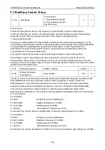
Output frequency increase or decrease according to the S curve. S curve is used in the pace with
gentle start or stop demand, such as elevator, conveyor belt, etc. Function code F1-28 and F1-29
respectively defined the time scale of inertial stage and finish stage of S curve
acceleration/deceleration.
2: S curve acceleration/deceleration B
In the S curve acceleration/deceleration B, rated motor frequency
f
b
always S curve inflection point.
As shown in figure 6-4. Generally used in the occasion that high-speed areas of above the rated
frequency need to be rapid acceleration/deceleration.
When set frequency above rated frequency, deceleration time is:
T
b
t
f
f
9
5
9
4
2
Among them, f is set frequency,
f
b
is the rated motor frequency, T is the time for 0 frequency
accelerate to
f
b
rated frequency.
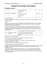
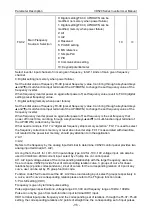
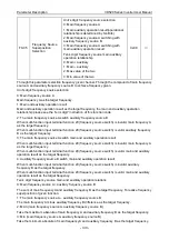
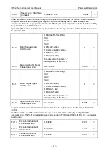
F1-28
Time Ratio of S Curve
Start Segment
0.0%~(100.0%-F1-26)
30.0%
◎
F1-29
Time Ratio of S Curve
End Segment
0.0%~(100.0%-F1-25)
30.0%
◎
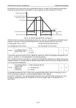
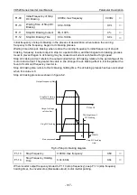
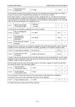
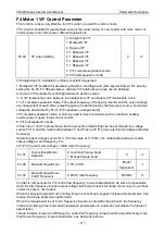
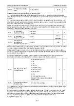
Function code F1-28 and F1-29 respectively defined the time scale of inertial stage and finish stage of
S curve acceleration/deceleration, two function code need to meet: F1-28+F1-29
≤100.0%
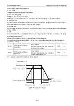
T1 in figure 6-4 is the F1-28 defined parameters, the slope of output frequency changes in this period
of time increased gradually. T2 is the F1-29 defined time, the slope of output frequency changes in
this period of time change to 0 gradually.
Between t1 and t2 time, the slope of output frequency changes is fixed, namely for linear
acceleration/deceleration in this stage.
t1
t1
t2
t2
Set frequency(f)
Output frequency(Hz)
Time(t)
S curve acceleration/deceleration A diagram


