VD520 Series Inverter User Manual Parameter Description
- 173 -
A0 Motor 1 Torque Control Parameter Group
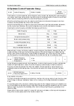
A0-00
Speed/Torque Control
Mode Selection
0: Speed control
1: Torque control
0
◎
Used to select the inverter control mode: speed control or torque control.
VD520
’s multi-function digital DI terminal, have two function associated with torque control: torque
control prohibit (function 40), speed control/torque control switch (function 39). The two terminals
should be use in conjunction with A0-00 to realize the switch between speed and torque control.
When the speed control/torque control switch terminal is invalid, the control mode is determined by
A0-00, if the speed control switch/torque control switch is effective, the control mode is equivalent to
the value of A0-00.
In any case, the frequency inverter is fixed to the speed control mode when the torque control prohibit
terminal is valid.
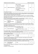
A0-01
Torque Setting Source
Selection under the
Torque Control Mode
0: Digital setting (A0-02)
1: AI1
2: AI2
3: Reserved
4: PULSE
5: Communication setting
6: MIN (AI1, AI2)
7: MAX (AI1, AI2)
8: Keypad Potentiometer (the full scale
of option 1~7 corresponding digital
setting of A0-02)
0
◎
A0-02
Torque Digital Setting
under the Torque Control
Mode
-200.0%~2000%
100.0%
○
A0-01 is used to select the torque setting source, a total of 8 kinds of torque setting method.
Torque setting use the relative value, and 100% corresponding the rated torque of the inverter. Set
range -200.0%~200.0%, which shows that frequency inverter maximum torque of the 2 times the
rated torque of the inverter.
When the torque is setting using 1~7, communication, analog input, and 100% of pulse input
corresponding A0-02.
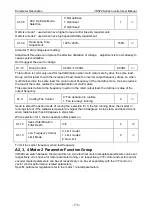
A0-03
Max Frequency Source
Selection under the
Torque Control Forward
0: Digital setting (A0-04)
1: AI1
2: AI2
3: Reserved
4: PULSE
5: Communication setting
6: Keypad potentiometer
0
◎
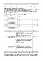
A0-04
Max Frequency Digital
Setting under the Torque
Control Forward
0.00Hz~max frequency
50.00Hz
○

