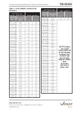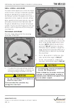
Lifting
Point
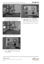
12. When the correct amount of support bases
are installed and secured to each other, the
tool must be lifted into position and placed
onto the support base(s). An eye bolt is
provided in the top-middle section of the
tool. Make sure the minimum capacity
rating of the overhead crane is 2000
pounds/910 kilograms.
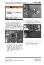
13. As the tool is being lowered onto the
support base(s), make sure the power cord
is guided out of the way to prevent damage
to the cord. The holes in the base of the
tool must align with the innermost holes in
the support base, as shown above.
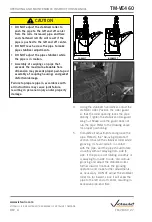
14. Locate the bolt, lock washer, and nut
(supplied with the support base kit). This
hardware is required to anchor the tool and
support base to each other.
15. Insert a bolt with a flat washer up through
the hole in the support base and into the
hole in the base of the tool. Apply a lock
washer and nut to the end of the bolt.
Tighten the nut completely until the lock
washer is compressed fully. Repeat this
step for the other three hole locations in
the support base and tool base.
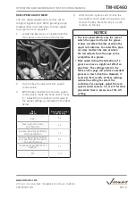
NOTICE
• VE460 tools are equipped with a
detachable safety-foot-switch cord. The
safety foot switch can be removed easily
for storage in the cabinet when the tool is
not is use.
TM-VE460_14
TM-VE460
OPERATING AND MAINTENANCE INSTRUCTIONS MANUAL
www.victaulic.com
VICTAULIC IS A REGISTERED TRADEMARK OF VICTAULIC COMPANY.
REV_A


