background image

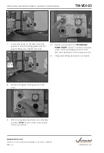
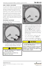
8.  If rotation of the lower roll is counter-

clockwise, turn the power switch on the 
side of the tool to the 

“OFF”

 position and 

proceed with the following steps.

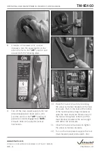
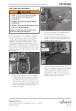
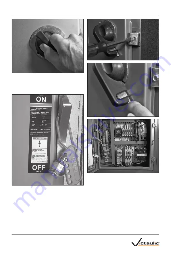
9.  Turn off the main power supply to the tool 

(main breaker panel, knife switch, etc.). 
Lock the switch in the 

“OFF”

 position to 

prevent accidental engagement. 

NOTE:


Victaulic does not supply this lockout 
mechanism.

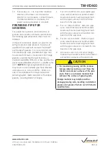
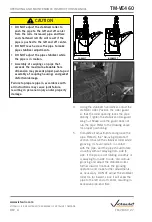
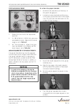
10.  Open the main enclosure by loosening 

the screw on the two brackets of the main 
enclosure. Push in the lever at the bottom 
of the handle while turning clockwise to 
open the main enclosure. Reverse any of 
the two incoming lines at the top of the 
main breaker (located at the upper-right 
side within the enclosure).

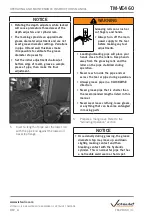
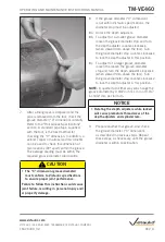
11.  Close the main enclosure and re-tighten 

the screw on the two brackets.

12.  Turn on the main power supply to the tool 

(main breaker panel, knife switch, etc.).

TM-VE460_19

TM-VE460

OPERATING AND MAINTENANCE INSTRUCTIONS MANUAL

www.victaulic.com

VICTAULIC IS A REGISTERED TRADEMARK OF VICTAULIC COMPANY.

REV_A

Summary of Contents for VE460

Page 1: ...and hearing protection while working around this tool Save this operating and maintenance manual If you need additional copies of any literature or if you have questions concerning the safe and proper operation of this tool contact Victaulic P O Box 31 Easton PA 18044 0031 Phone 1 800 PICK VIC E Mail pickvic victaulic com WARNING VE460 PIPE ROLL GROOVING TOOL TM VE460 www victaulic com VICTAULIC I...

Page 2: ......

Page 3: ...ended Lubricants 53 Bearing and Slide Grease 53 Gear Oil 53 Hydraulic Oil 53 Parts Ordering Information 53 Troubleshooting 54 Tool Rating and Roll Selection 56 Original Groove System and ES Rolls for Steel and Schedule 40 Stainless Steel Pipe Color Coded Black 56 Original Groove System Rolls for Aluminum and PVC Plastic Pipe Color Coded Yellow Zinc 58 Original Groove System Rolls for Schedule 5S a...

Page 4: ...ion of these tools The operator is cautioned to always practice safety first during each phase of use including setup and maintenance It is the responsibility of the owner lessee or user of these tools to ensure that all operators read this manual and fully understand the operation of these tools Read this manual before operating or servicing these tools Become familiar with the tool s operations ...

Page 5: ...ontact Victaulic 15 Keep hands and tools away from grooving rolls and stabilizer roller during the grooving operation Grooving rolls can crush or cut fingers and hands 16 Do not reach inside the pipe ends during tool operation Pipe edges can be sharp and can snag gloves hands and shirt sleeves Fingers and hands can be crushed between the pipe and lower roll 17 Do not over reach Maintain proper foo...

Page 6: ...E460 tools are palletized individually and enclosed in a wooden or cardboard sleeve which is designed for use in re shipping the tool back to Victaulic upon completion of the rental contract when applicable The stabilizer assembly and additional roll sets are shipped in a separate container Upon receipt of the tool make sure all necessary parts are included If any parts are missing contact Victaul...

Page 7: ... in the operating and maintenance manual Never wear loose clothing loose gloves or anything that can become entangled in moving parts 5037 Rev C R091424LAB Contact with hazardous voltage inside this cover plate may result in death or serious personal injury ALWAYS disconnect the tool from the power source before performing maintenance or adjustments Only qualified personnel should open this cover ...

Page 8: ...or or base After an appropriate location is chosen the tool must be level and securely anchored A non level tool can severely affect grooving operation When checking tool level place the level directly on the frame of the tool as shown above 3 Select a location for the tool and pipe stand by taking into consideration the following factors 50 80 inches 1290 mm 30 30 inches 770 mm 26 00 inches 660 m...

Page 9: ...er assembly onto the front right corner of the tool so that the mounting holes in the stabilizer assembly align with the mounting holes in the tool Using the stabilizer bolts and lock washers removed previously from the tool fasten the stabilizer assembly to the tool NOTE The tool frame is designed so that no nuts are required on the ends of the bolts Tighten all stabilizer bolts completely until ...

Page 10: ...nd Smaller Pipe Sizes section For the 24 inch 610 0 mm and smaller pipe size range support bases are not required but the tool must be anchored to a sturdy level concrete floor If the tool will be used for roll grooving 26 inch 660 0 mm and larger pipe sizes follow the Tool Setup for Grooving 26 inch 660 0 mm and Larger Pipe Sizes section NOTE Each support base is 12 inches 305 mm in height and we...

Page 11: ... section 2 The VE460 Roll Grooving Tool with support base s is designed for use in a permanent location and must be located on a level concrete floor After an appropriate location is chosen the bottom support base must be level and securely anchored A non level tool can severely affect grooving operation 3 Select a location for the tool support base s and pipe stand by taking into consideration th...

Page 12: ... designed so that no nuts are required on the ends of the bolts Tighten all stabilizer bolts completely until the lock washers are compressed fully Anchor Nut Flat Washer 5 Wedge type concrete floor anchors 5 8 x 41 4 inch size must be used to secure the bottom platform to the floor Make sure the floor anchors are installed into the concrete floor in accordance with the manufacturer s instructions...

Page 13: ...rt base 9 Locate the bolt lock washer and nut supplied with the support base kit This hardware is required to anchor the support bases to each other 10 Insert a bolt up through the hole in the bottom support base and into the hole in the second support base Apply a lock washer and nut to the end of the bolt Tighten the nut completely until the lock washer is compressed fully Repeat this step for t...

Page 14: ...olt lock washer and nut supplied with the support base kit This hardware is required to anchor the tool and support base to each other 15 Insert a bolt with a flat washer up through the hole in the support base and into the hole in the base of the tool Apply a lock washer and nut to the end of the bolt Tighten the nut completely until the lock washer is compressed fully Repeat this step for the ot...

Page 15: ...les in the support base as shown above Repeat this step for the other side of the tool Lock Washer 16 Total Hex Head Bolt 16 Total Handrail Base 8 Total Platform 2 Total Handrail 4 Total Hex Nut 16 Total 18 Install a handrail base onto the platform at the eight locations on the platform tool support Make sure the holes in the handrail bases align with the holes in the platforms support base and th...

Page 16: ...own above 18d Tighten the two set screws on each handrail base to retain the handrails 19 Installation of the support base s is now complete Proceed to the Power Requirements section TM VE460_16 TM VE460 OPERATING AND MAINTENANCE INSTRUCTIONS MANUAL www victaulic com VICTAULIC IS A REGISTERED TRADEMARK OF VICTAULIC COMPANY REV_A ...

Page 17: ...TATION DIRECTION Each VE460 Roll Grooving Tool is provided with a label inside the main electrical enclosure which identifies voltage ratings etc for the tool refer to example below Reference must be made to this label to ensure proper tool setup MODEL VOLTS PHASE HERTZ FULL LOAD CURRENT SERIAL NUMBER 208 230 440 460 1 3 380 400 AMPS AT 230 VOLTS AMPS AT 460 VOLTS AMPS AT 380 VOLTS 50 60 50 60 GEA...

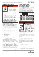
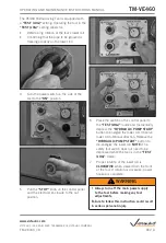
Page 18: ...MP START button to energize the lower roll Observe lower roll rotational direction Release the HYDRAULIC PUMP START button to de energize the lower roll NOTE The safety foot switch does not need to be depressed while the tool is in the TEST JOG mode 7 Proper rotation of the lower roll is CLOCKWISE when viewed from the front of the tool If rotation is clockwise power hookup is complete WARNING Alwa...

Page 19: ...e by loosening the screw on the two brackets of the main enclosure Push in the lever at the bottom of the handle while turning clockwise to open the main enclosure Reverse any of the two incoming lines at the top of the main breaker located at the upper right side within the enclosure 11 Close the main enclosure and re tighten the screw on the two brackets 12 Turn on the main power supply to the t...

Page 20: ...gaskets including AGS Vic Flanges 1 For 12 inch 323 9 mm and smaller pipe sizes raised internal and external weld beads and seams must be ground flush with the pipe surface 2 inches 50 mm back from the pipe ends 1a For 14 38 inch 355 6 965 mm pipe sizes raised internal and external weld beads and seams must be ground flush with the pipe surface 4 inches 100 mm back from the pipe ends 1b For 40 60 ...

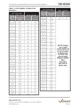
Page 21: ...pe stands Refer to the Long Pipe Lengths section for instructions on how to groove long pipe lengths If pipe is required that is shorter than the minimum length listed in Table 1 shorten the next to last piece so that the last piece is as long or longer than the minimum length specified EXAMPLE A 20 foot 4 inch 6 2 m length of 10 inch diameter steel pipe is required to finish a section and only 20...

Page 22: ... 460 14 OD 14 000 12 16 355 6 305 410 377 0 mm 14 843 12 16 377 0 305 410 15 OD 15 000 12 16 381 0 305 410 16 OD 16 000 12 16 406 4 305 410 Steel Stainless Steel Aluminum and PVC Pipe Size Length inches mm Nominal Pipe Size inches or mm Actual Outside Diameter inches mm Minimum Maximum 426 0 mm 16 772 12 16 426 0 305 410 18 OD 18 000 NOTE Always use a pipe stand when roll grooving pipe in these si...

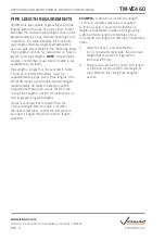
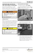
Page 23: ...he proper rolls are not installed on the tool refer to the Roll Changing section CAUTION Make sure the lower roll retaining bolt is tight A loose lower roll retaining bolt could cause damage to the tool and rolls ADJUSTING THE ROLL GUARDS The VE460 tool features a SET GUARD control switch setting With the correct pipe size and schedule inserted in the tool the SET GUARD setting allows the operator...

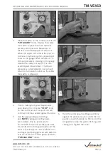
Page 24: ... down in on the red STOP knob on the control panel The upper roll will continue to remain seated against the pipe 5 Use the appropriate guard setting pad NOTE Two guard setting pads are included One is specifically for 12 inch 323 9 mm and smaller pipe sizes 1 4 inch 6 4 mm thick guard pad and the other is specifically for 14 inch 355 6 mm and larger pipe being grooved with AGS roll sets 3 8 inch ...

Page 25: ...ll the STOP knob on the control panel to the out position 10 Depress and release the HYDRAULIC PUMP START button The tool s hydraulic pump motor will energize and the tool s ram shaft will retract to the neutral position 11 The guard setting procedure is complete TM VE460_25 TM VE460 OPERATING AND MAINTENANCE INSTRUCTIONS MANUAL www victaulic com VICTAULIC IS A REGISTERED TRADEMARK OF VICTAULIC CO...

Page 26: ...acting the stabilizer 1 Make sure the proper roll set is installed on the tool for the pipe size and material to be grooved Rolls are marked with the pipe size part number and they are color coded according to the pipe material Refer to the applicable Tool Rating and Roll Selection section 2 Loosen the stabilizer locking handle and the stabilizer roller guard wing nut 2a Using the stabilizer handw...

Page 27: ...er guard so that the roller opening faces the pipe directly Tighten the stabilizer roller guard wing nut Make sure the guard does not rub the pipe Refer to the drawing above for proper positioning 5 Complete all adjustments and groove the pipe Refer to the Grooving Operation section Observe the stabilizer roller while grooving It should remain in contact with the pipe and the pipe should rotate sm...

Page 28: ...3 0 PVC 10 0 4 After the ram speed is set re lock the ram speed control valve into position and remove the key Store the key in a safe location on the tool NOTICE The ram speed affects only the rate at which the upper roll forms the groove It does not affect the rate at which the upper roll advances to contact the pipe nor does it affect the rate at which the roll retracts from the pipe at the com...

Page 29: ...ps head screwdriver to adjust the range screw Failure to follow this instruction may damage the screw head 2 If necessary rotate the time range screw located in the lower left hand corner of the timer to the desired range shown on the dial face NOTE VE460 tools are factory set in the SEC 10 position Use only a 0 Phillips head screwdriver to adjust the range screw Use of any tools other than a 0 Ph...

Page 30: ...that are the proper material diameter and thickness to be grooved Make sure the scrap sections meet the length requirements listed in Table 1 To achieve the proper diameter 1 Determine the diameter and thickness of the pipe to be grooved 2 Locate the proper diameter and thickness on the pipe size indicator label of the depth stop The pipe size indicator barrel can be rotated for easy viewing Depth...

Page 31: ...Loading unloading pipe will place your hands close to the rollers Keep hands away from the grooving rolls and the roller on the pipe stabilizer during operation Never reach inside the pipe ends or across the tool or pipe during operation Always groove pipe in a CLOCKWISE direction Never groove pipe that is shorter than the recommended lengths listed in this manual Never wear loose clothing loose g...

Page 32: ...ust for a smaller groove diameter loosen the groove diameter stop and turn the depth adjuster counter clockwise when viewed from above the tool Turn the groove diameter stop counter clockwise to lock the depth adjuster in this position 8c To adjust for a larger groove diameter loosen the loosen the groove diameter stop and turn the depth adjuster clockwise when viewed from above the tool Turn the ...

Page 33: ...sulting in reduced tool life and or damage to the tool 1 Before grooving make sure all instructions in the previous sections of this manual have been followed 2 Turn on the main power supply to the tool main breaker panel knife switch etc 3 Turn the power switch on the side of the tool to the ON position 4 Make sure the switch on the control panel is set to the GROOVE position 4a Pull the STOP kno...

Page 34: ...the groove diameter stop may move up and down slightly making contact and then breaking contact with the hydraulic cylinder This is normal for pipe that has a noticeable weld seam or hard spot 7 As grooving continues the groove diameter stop will move down and contact the hydraulic cylinder This contact activates the dwell timer which allows the pipe to rotate one to three more revolutions to ensu...

Page 35: ...owing the pipe to rotate freely 1 Make sure the tool is level Refer to the Tool Setup section for leveling requirements 10ft 1ft 0ft 3m 0 3m 0m Exaggeratedforclarity Tool and Pipe Centerline Level 20 foot 6 meter Length of Pipe 2 Place the pipe stand at a distance slightly beyond half the pipe length from the tool Refer to the drawing above Pipeangle exaggeratedforclarity Tool Centerline 0 to Max ...

Page 36: ...switch on the side of the tool to the ON position 8 Pull the STOP knob on the control panel and the electrical enclosure to the out position 9 Make sure the switch on the control panel is set to the GROOVE position 9a Push the HYDRAULIC PUMP START button TM VE460_36 TM VE460 OPERATING AND MAINTENANCE INSTRUCTIONS MANUAL www victaulic com VICTAULIC IS A REGISTERED TRADEMARK OF VICTAULIC COMPANY REV...

Page 37: ...e pipe end contacts the lower roll backstop flange completely Remove hands from the pipe 11 The operator should be positioned as shown above 12 To start the grooving operation depress and hold down the safety foot switch This will advance the upper roll into contact with the pipe The lower roll will start rotating and the groove will begin to form 13 During the grooving operation visually check th...

Page 38: ...e performed for a while turn off the hydraulic system by pushing down in either the red STOP knob on the control panel or the electrical enclosure NOTICE If the pipe remains lodged on the lower roll Jogging the lower roll will free the pipe DO NOT attempt to pull the pipe out of the rolls while jogging the lower roll Pull the STOP knob on the control panel and the electrical enclosure to the out p...

Page 39: ...urn on the main power supply to the tool main breaker panel knife switch etc 2 Turn the power switch on the side of the tool to the ON position 3 Pull the STOP knob on the control panel and the electrical enclosure to the out position 4 Push the HYDRAULIC PUMP START button 5 Depress the safety foot switch When the groove diameter stop contacts the hydraulic cylinder push down in on the red STOP kn...

Page 40: ...MP START button to retract raise the slide 9 After the slide is retracted raised completely push down in on the red STOP knob on the control panel 10 Turn the power switch on the side of the tool to the OFF position TM VE460_40 TM VE460 OPERATING AND MAINTENANCE INSTRUCTIONS MANUAL www victaulic com VICTAULIC IS A REGISTERED TRADEMARK OF VICTAULIC COMPANY REV_A ...

Page 41: ...nnot be removed by hand use a conventional gear puller UPPER ROLL REMOVAL 1 Adjust the front roll guard downward if necessary to fully uncover the upper shaft 2 Pull the upper shaft pin out of the slide until it stops 3 While supporting the upper roll remove the upper shaft from the upper roll slide by pulling it straight out TM VE460_41 TM VE460 OPERATING AND MAINTENANCE INSTRUCTIONS MANUAL www v...

Page 42: ... roll behind the slide as shown above Make sure the markings on the upper roll are facing forward While supporting the upper roll insert the upper shaft into the slide and upper roll 3 Align the hole in the upper shaft with the hole in the side of the slide Push the upper shaft pin into the slide upper shaft until it stops NOTE Hole orientation lines are marked on the front of the upper shaft TM V...

Page 43: ...shaft with the square hole in the lower roll Push the lower roll completely onto the main shaft Make sure the markings on the lower roll are facing out 4 Install the lower roll washer and lower roll retaining bolt 5 Tighten the lower roll retaining bolt completely to secure the lower roll onto the main shaft 6 Turn the power switch on the side of the tool to the ON position TM VE460_43 TM VE460 OP...

Page 44: ...pper roll and slide will start to move downward 9 After the upper roll slide has advanced approximately 1 inch 25 mm and the rolls are aligned and engaged push down in on the red STOP knob on the control panel 10 Snap the slide spacer into the tool as shown above TM VE460_44 TM VE460 OPERATING AND MAINTENANCE INSTRUCTIONS MANUAL www victaulic com VICTAULIC IS A REGISTERED TRADEMARK OF VICTAULIC CO...

Page 45: ...ase through the lubrication fitting on the front of the upper shaft Refer to the applicable Recommended Lubricants table for the proper grease 15 Roll set installation is now complete Before grooving make sure all instructions in the previous sections of this manual have been followed i e adjusting the roll guards adjusting the groove diameter stop etc TM VE460_45 TM VE460 OPERATING AND MAINTENANC...

Page 46: ...8 hours of operation lubricate the tool Always lubricate the upper roll bearings when rolls are changed 2 Grease the upper shaft bearings every time roll changes are made and after every 8 hours of operation A grease fitting is provided on the front of the upper shaft Refer to the applicable Recommended Lubricants table for the proper grease 3 Grease the slide gibs The slide gib grease fitting is ...

Page 47: ... the plug from the top of the gear reducer and fill to the proper level refer to drawing above Refer to the card attached to the gear reducer for the proper lubricant 3 Re install the plug s CHECKING AND FILLING HYDRAULIC OIL 1 Check the hydraulic oil level on a monthly basis The level should be 1 2 inches 25 50 mm below the top of the tank DO NOT over fill the tank since the oil may overflow due ...

Page 48: ...sen and remove the screw on top of the reservoir There is no need to loosen the screw that holds the bracket to the frame 5 Remove the fill vent plug from the top of the reservoir 6 Slide the reservoir partially over the side of the tool DO NOT disconnect any electrical or hydraulic lines 7 Position a container underneath the drain plug Make sure the container is large enough to hold 2 gallons 8 l...

Page 49: ...ll the filter with oil Install the new filter hand tight 12 Fill the tank with new hydraulic oil to 1 2 inches 25 50 mm from the top of the tank Refer to the applicable Recommended Lubricants table 13 Install the fill vent plug 14 Turn on the main power supply to the tool main breaker panel knife switch etc TM VE460_49 TM VE460 OPERATING AND MAINTENANCE INSTRUCTIONS MANUAL www victaulic com VICTAU...

Page 50: ... out position 17 Push the HYDRAULIC PUMP START button 18 Check the hydraulic oil level Add oil as necessary 19 Push down in on the red STOP knob on the control panel 20 Follow the Air Bleeding section TM VE460_50 TM VE460 OPERATING AND MAINTENANCE INSTRUCTIONS MANUAL www victaulic com VICTAULIC IS A REGISTERED TRADEMARK OF VICTAULIC COMPANY REV_A ...

Page 51: ...e tee as shown above Insert the other end of the bleeder tube into the fill vent hole in the hydraulic tank NOTE The bleeder tube consists of a 1 4 inch NPT barb hose fitting and 4 feet 1 2 m of 1 4 inch ID clear vinyl hose supplied with the tool 5 Turn on the main power supply to the tool main breaker panel knife switch etc 6 Turn the power switch on the side of the tool to the ON position TM VE4...

Page 52: ...l tube 10 Push down in on the red STOP knob on the control panel NOTICE To prevent oil from flowing out of the tee while removing the bleeder tube and installing the plug Block the groove diameter stop from moving down by inserting a piece of wood between the groove diameter stop and the top of the hydraulic cylinder 11 Remove the bleeder tube and install the plug into the tee DO NOT ALLOW AIR TO ...

Page 53: ... Refer to the tag located on the gear reducer HYDRAULIC OIL High Pressure Anti Wear Anti Foam Hydraulic Oil ISO Grade 32 Manufacturer Product BP Amoco Energol HLP HM32 Gulf Oil Corp Harmony 32 AW Kendall Refining Co Kenoil R O AW 32 Lubriplate HO o Mobil Oil Corp Mobil DTE 24 Pennzoil Products Co Pennzbell AW32 Shell Oil Co Tellus 32 Sun Refining Survis 832 Texaco Inc Rando PARTS ORDERING INFORMAT...

Page 54: ...ng grooving loud thumps or bangs occur approximately once every revolution of the pipe Pipe has a pronounced weld seam For 12 inch 323 9 mm and smaller pipe sizes raised internal and external weld beads and seams must be ground flush with the pipe surface 2 inches 50 mm back from the pipe ends For 14 38 inch 355 6 965 mm pipe sizes raised internal and external weld beads and seams must be ground f...

Page 55: ...e Tool Rating and Roll Selection section The A Gasket Seat or B GrooveWidth dimensions do not meetVictaulic specifications Upper roll bearing is not lubricated adequately Refer to the Maintenance section Incorrect upper roll lower roll or both installed on the tool Install the correct rolls Refer to the applicable Tool Rating and Roll Selection section Pipe not inserted fully onto the lower roll o...

Page 56: ...4 0 375 0 250 0 365 273 0 3 4 9 5 6 4 9 3 12 12 750 0 156 0 375 0 250 0 375 323 9 4 0 9 5 6 4 9 5 14 OD 14 000 0 156 0 375 0 312 0 375 Lower Roll R914460L16 Upper Roll R9Q1448U16 Roll Set R9Q1460016 355 6 4 0 9 5 7 9 9 5 16 OD 16 000 0 165 0 375 0 312 0 375 406 4 4 2 9 5 7 9 9 5 18 OD 18 000 0 165 0 375 0 375 0 375 Lower Roll R918460L20 Upper Roll R9Q1448U20 Roll Set R9Q1460020 457 0 4 2 9 5 9 5 9...

Page 57: ...t or near the maximum rated thickness the pipe must not exceed the yield strength of API 5L Grade B ASTM Grade B 150 Brinell Hardness Number BHN maximum Types 304 304L and 316 316L stainless steel pipe The wall thicknesses listed are nominal minimum and maximum In addition the following pipe sizes may be roll grooved 108 0mm 133 0mm 139 7mm 152 4mm 159 0mm 165 1mm 203 2 mm 216 3 mm 254 0 mm 267 4 ...

Page 58: ...l RPQ1448U12 Roll Set RPQ1460012 219 1 2 8 8 2 8 2 8 2 10 10 750 0 134 0 250 273 0 3 4 6 4 12 12 750 0 156 0 250 323 9 4 0 6 4 Aluminum Alloys 6061 T4 and 6063 T4 PVC Type 1 Grade 1 PVC 1120 PVC Type 1 Grade II PVC 1220 PVC Type II Grade 1 PVC 2116 The wall thicknesses listed are nominal minimum and maximum For aluminum pipe the following additional pipe sizes may be roll grooved 108 0mm 133 0mm 1...

Page 59: ...U16 Roll Set RXQ1460016 355 6 4 0 4 8 6 4 16 OD 16 000 0 165 0 188 0 250 406 4 4 2 4 8 6 4 18 OD 18 000 0 165 0 188 0 250 Lower Roll RX18460L20 Upper Roll RXQ1448U20 Roll Set RXQ1460020 457 0 4 2 4 8 6 4 20 OD 20 000 0 188 0 218 0 250 508 0 4 8 5 5 6 4 22 OD 22 000 0 188 0 218 0 250 Lower Roll RX22460L24 Upper Roll RXQ1448U24 Roll Set RXQ1460024 559 0 4 8 5 5 6 4 24 OD 24 000 0 218 0 250 0 250 610...

Page 60: ... OD 18 000 0 220 0 500 0 165 0 188 457 0 5 6 12 7 4 2 4 8 20 OD 20 000 0 220 0 500 0 188 0 218 Lower Roll RW0X460L24 Upper Roll RWQX448U24 Roll Set RWQX460024 508 0 5 6 12 7 4 8 5 5 24 OD 24 000 0 220 0 500 0 218 0 250 610 0 5 6 12 7 5 5 6 4 26 OD 26 000 0 220 0 500 Lower Roll RWQ3460L38 Upper Roll RWQ3460U38 Roll Set RWQ3460038 660 0 5 6 12 7 28 OD 28 000 0 220 0 500 711 0 5 6 12 7 30 OD 30 000 0...

Page 61: ...e The wall thicknesses listed are nominal minimum and maximum The wall thicknesses listed in this column are for Schedule 10S stainless steel pipe In addition stainless steel pipe in 14 24 inch OD sizes is available in true Schedule 10 which has a nominal wall thickness of 0 250 inch 6 4 mm For grooving 14 24 inch OD true Schedule 10 stainless steel pipe nominal wall thickness of 0 250 inch 6 4 mm...

Page 62: ...as dirt chips rust and scale that may interfere with proper coupling assembly For pipe being grooved to AGS specifications the corners at the bottom of the groove must be radiused R 09 inch R2 3 mm The Groove Width B dimension will be achieved with properly maintained Victaulic tools that are equipped with special Victaulic AGS RW or RWX roll sets C Dimension The C dimension is the proper diameter...

Page 63: ...135 9 139 7 mm 5 500 5 556 5 469 0 625 0 656 0 594 0 344 0 375 0 313 5 334 5 314 0 083 0 078 5 60 139 7 141 1 138 9 15 9 16 7 15 1 8 7 9 5 8 0 135 5 135 0 2 2 2 0 142 2 5 5 563 5 619 5 532 0 625 0 656 0 594 0 344 0 375 0 313 5 395 5 373 0 084 0 078 5 66 141 3 142 7 140 5 15 9 16 7 15 1 8 7 9 5 8 0 137 0 136 5 2 2 2 0 143 8 152 4 mm 6 000 6 056 5 969 0 625 0 656 0 594 0 344 0 375 0 313 5 830 5 808 ...

Page 64: ... 785 0 094 0 134 10 17 254 0 255 6 253 2 19 1 19 8 18 3 11 9 12 7 11 1 249 2 248 5 2 4 3 4 258 3 267 4 mm 10 528 10 591 10 497 0 750 0 781 0 719 0 469 0 500 0 438 10 340 10 313 0 094 0 134 10 70 267 4 269 0 266 6 19 1 19 8 18 3 11 9 12 7 11 1 262 6 262 0 2 4 3 4 271 8 10 10 750 10 813 10 719 0 750 0 781 0 719 0 469 0 500 0 438 10 562 10 535 0 094 0 134 10 92 273 0 274 7 272 3 19 1 19 8 18 3 11 9 1...

Page 65: ...0 0 590 0 320 0 300 6 455 6 433 0 085 0 280 6 730 168 3 169 9 167 5 15 5 15 0 8 1 7 6 164 0 163 4 2 2 7 1 170 9 8 8 625 8 688 8 594 0 719 0 699 0 410 0 390 8 441 8 416 0 092 0 322 8 800 219 1 220 7 218 3 18 3 17 8 10 4 9 9 214 4 213 8 2 3 8 2 223 5 10 10 750 10 813 10 719 0 719 0 699 0 410 0 390 10 562 10 535 0 094 0 365 10 920 273 0 274 7 272 3 18 3 17 8 10 4 9 9 268 3 267 6 2 4 9 3 277 4 12 12 7...

Page 66: ... to accommodate this growth EXAMPLE If you need a 24 inch 610 mm length of pipe that will contain an AGS groove at each end cut the pipe to a length of 233 4 inches 603 mm to allow for this growth It is critical to measure the Groove Diameter C dimension along with the Gasket Seat A dimension and the Flare Diameter F dimension These measurements must be within the specifications listed in the foll...

Page 67: ...36 5 11 6 11 7 11 4 596 9 595 8 615 4 26 26 094 25 969 1 750 1 781 1 687 0 535 0 540 0 530 25 430 25 370 26 30 660 0 662 8 659 6 44 5 45 2 42 8 13 6 13 7 13 5 645 9 644 4 668 0 28 28 094 27 969 1 750 1 781 1 687 0 535 0 540 0 530 27 430 27 370 28 30 711 0 713 6 710 4 44 5 45 2 42 8 13 6 13 7 13 5 696 7 695 2 718 8 30 30 094 29 969 1 750 1 781 1 687 0 535 0 540 0 530 29 430 29 370 30 30 762 0 764 4...

Page 68: ...4 3 61 9 14 3 14 4 14 1 1355 7 1354 2 1379 2 56 56 094 55 969 2 500 2 531 2 437 0 562 0 567 0 557 55 375 55 315 56 30 1422 0 1424 8 1421 6 63 5 64 3 61 9 14 3 14 4 14 1 1406 5 1405 0 1430 0 60 60 094 59 969 2 500 2 531 2 437 0 562 0 567 0 557 59 375 59 315 60 30 1524 0 1526 4 1523 2 63 5 64 3 61 9 14 3 14 4 14 1 1508 1 1506 6 1531 6 The Groove Width B dimension is listed for information only The G...

Page 69: ...500 1 531 1 437 0 455 0 460 0 450 17 500 17 455 18 23 457 0 459 6 456 4 38 1 38 9 36 5 11 6 11 7 11 4 444 5 443 4 463 0 20 20 000 20 125 19 969 1 500 1 531 1 437 0 455 0 460 0 450 19 500 19 455 20 23 508 0 511 2 507 2 38 1 38 9 36 5 11 6 11 7 11 4 495 3 494 2 513 8 24 24 000 24 125 23 969 1 500 1 531 1 437 0 455 0 460 0 450 23 500 23 455 24 23 610 0 612 8 608 8 38 1 38 9 36 5 11 6 11 7 11 4 596 9 ...

Page 70: ......

Page 71: ......

Page 72: ...com TM VE460 5855 REV A UPDATED 10 2009 RM00460000 VICTAULIC IS A REGISTERED TRADEMARK OF VICTAULIC COMPANY 2009 VICTAULIC COMPANY ALL RIGHTS RESERVED PRINTED IN THE USA VE460 PIPE ROLL GROOVING TOOL TM VE460 OPERATING AND MAINTENANCE INSTRUCTIONS MANUAL ...

Reviews: