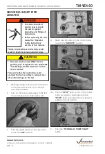
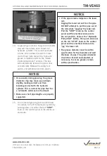
NOTICE
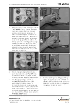
• Rotating the depth adjusters while locked
will cause premature thread wear of the
depth adjusters and cylinder ram.
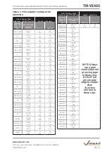
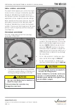
• The markings provide an approximate
groove diameter adjustment and are not
exact groove diameter settings. Variations
in pipe OD and wall thickness make
it impossible to calibrate the groove
diameter stop exactly.
• Set the initial adjustment shallow (at
bottom edge of mark), groove a sample
piece of pipe, then make the final
adjustment.
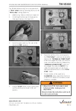
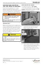
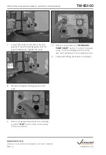
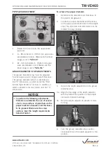
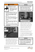
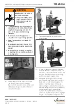
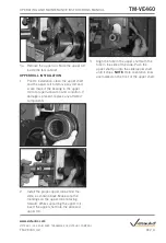
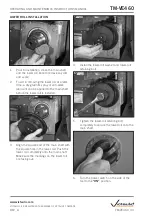
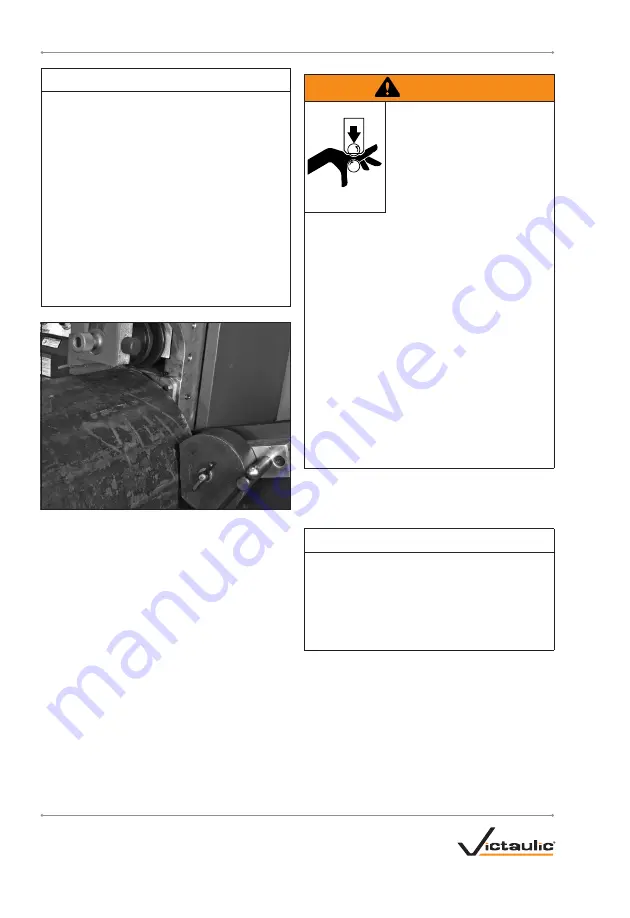
5. Insert a length of pipe over the lower roll
with the pipe end against the lower-roll
backstop flange.
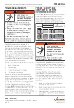
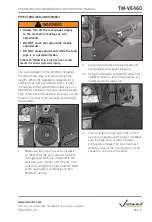
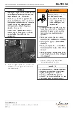
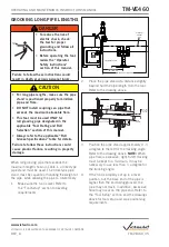
WARNING
Grooving rolls can crush or
cut fingers and hands.
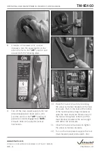
• Always turn off the main
power supply to the tool
before making any tool
adjustments.
• Loading/unloading pipe will place your
hands close to the rollers. Keep hands
away from the grooving rolls and the
roller on the pipe stabilizer during
operation.
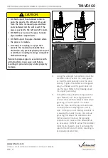
• Never reach inside the pipe ends or
across the tool or pipe during operation.
• Always groove pipe in a CLOCKWISE
direction.
• Never groove pipe that is shorter than
the recommended lengths listed in this
manual.
• Never wear loose clothing, loose gloves,
or anything that can become entangled
in moving parts.
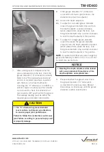
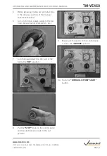
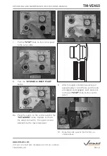
6. Prepare a trial groove. Refer to the
“Grooving Operation” section.
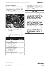
NOTICE
• Occasionally during grooving, the groove
diameter stop may move up and down
slightly, making contact and then
breaking contact with the hydraulic
cylinder. This is normal for pipe that has
a noticeable weld seam or hard spot.
TM-VE460_31
TM-VE460
OPERATING AND MAINTENANCE INSTRUCTIONS MANUAL
www.victaulic.com
VICTAULIC IS A REGISTERED TRADEMARK OF VICTAULIC COMPANY.
REV_A


