3a. The required power supply (refer to the
“Power Requirements” section)
3b. Ambient temperature requirements of 20º
F to 104º F/-21ºC to 26º C
3c. A level concrete floor or base for the tool
and pipe stand
3d. Adequate space to handle pipe lengths
3e. Adequate clearance around the tool and
stabilizer assembly for adjustment and
maintenance (refer to drawings on following
page)
WARNING
• During tool setup, two people are needed
to safely handle the stabilizer assembly
due to its weight.
• An alternative is to use a hoist to lift the
stabilizer assembly into position.
Failure to follow these instructions could
result in serious personal injury.
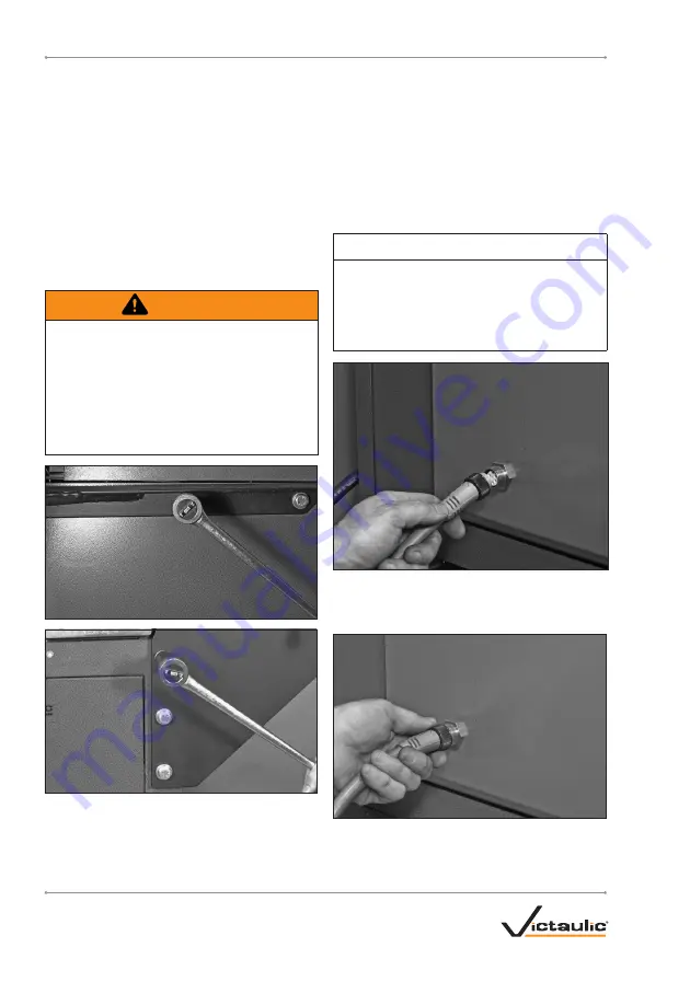
4. Remove the stabilizer bolts and lock
washers from the front and right side of the
tool. Position the stabilizer assembly onto
the front, right corner of the tool so that the
mounting holes in the stabilizer assembly
align with the mounting holes in the tool.
Using the stabilizer bolts and lock washers,
removed previously from the tool, fasten
the stabilizer assembly to the tool.
NOTE:
The tool frame is designed so that no nuts
are required on the ends of the bolts.
Tighten all stabilizer bolts completely until
the lock washers are compressed fully.
NOTICE
• VE460 tools are equipped with a
detachable safety-foot-switch cord. The
safety foot switch can be removed easily
for storage in the cabinet when the tool is
not in use.
5. Install the safety foot switch by aligning the
pins/tab of the male adapter plug with the
receptacle.
6. Tighten the locking ring on the plug.
7.
Proceed to the “Power Requirements”
section.
TM-VE460_9
TM-VE460
OPERATING AND MAINTENANCE INSTRUCTIONS MANUAL
www.victaulic.com
VICTAULIC IS A REGISTERED TRADEMARK OF VICTAULIC COMPANY.
REV_A


