background image

PARTS, SERVICE

& REPAIR BULLETIN

Issue Date:

 March 2011

Revision:

 D

Form No.: 

0056-1966

ESS3

ESS4

ESS7

EST4

ESL4

ELC4

Pressure Regulators

Summary of Contents for EDGE ELC4

Page 1: ...PARTS SERVICE REPAIR BULLETIN Issue Date March 2011 Revision D Form No 0056 1966 ESS3 ESS4 ESS7 EST4 ESL4 ELC4 Pressure Regulators...

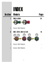
Page 2: ...INDEX Section Models Page 1 2 3 4 5 ESS3 ESS4 ESS7 EST4 ESL4 ELC4 Future EDGE Models Future EDGE Models Future EDGE Models i 01 15...

Page 3: ...own protection and the protection of your investment specify and use only VICTOR genuine parts and accessories It s the only way to guarantee the level of performance safety and reliability that you e...

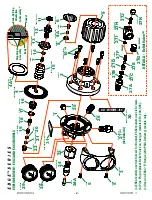
Page 4: ...NNET DECAL GAS 30 REAR BODY DECAL GAS I D 31 SEAT GUIDE 22 See Detail A BACK UP RING 4A c Diaphragm Assembly Body Bonnet Back Up Ring Orientation In Assembly c EXPLODED VIEW ESS3 AND ESS4 MODELS LOCK...

Page 5: ...ter 1 24A Inlet Filter 1 25 Pipe Plug 1 26 Outlet Connection 1 27 Relief Valve 1 28 Gauge Low Pressure 1 29 Gauge High Pressure 1 30 Decal Bonnet Gas I D 1 31 Decal Rear Body Gas Info 1 a Cylinder mod...

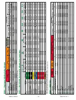
Page 6: ...2 0085 0702 0068 0740 0158 0740 0131 0972 0015 0972 0009 0960 0014 1415 0807 1415 0806 Carbon Dioxide CGA 320 d GREY 0790 0212 0790 0206 0702 0085 0702 0068 0740 0158 0740 0131 0985 0030 0985 0058 d 0...

Page 7: ...pring 19 Gland 20 Friction Damper 21 and Bottom Guide 22 from the Body 7 Remove the Relief Valve or Pipe Plug 27 Outlet Connection 26 and Pipe Plug 25 if necessary from the Body 8 Screw the Leverage B...

Page 8: ...tice for Cleaning Methods and Cleanliness Levels for Material and Equipment Used in Oxygen Enriched Environments ASTM G 127 Standard Guide for the Selection of Cleaning Agents for Oxygen Systems For m...

Page 9: ...verage Bar Tool RT 180 into the outlet port of the Body light hand tight and then use the Leverage Bar to tighten the Body onto the Inlet Connection At this point tighten enough so that the body canno...

Page 10: ...mly pushed up in place inside the Gland Then install the preassembled seat components into the Regulator Body with the Friction Damper and Gland fitting down into the cup shape of the Bottom Guide 15...

Page 11: ...129 to the top surface of the Bonnet the surface around the square of the Drive Screw then slip the Knob 9 into position with the square hole inside the knob mating to the square shaft of the Drive S...

Page 12: ...anifold Valve two or three times to remove contamination that may cause malfunctions Leave the Manifold Valve closed a If no flow comes through the Regulator determine the cause refer to the TROUBLESH...

Page 13: ...over again Refer to TROUBLESHOOTING CHART for more detailed cause and possible corrective action information 9 DROP TEST a With the Test Gun closed and the Manifold Valve open adjust the Regulator to...

Page 14: ...c Outlet Connection plugged Inspect and clear the Outlet Connection of any debris d Broken Adjusting Spring Replace the Adjusting Spring e Broken Seat Stem Replace the Seat Assembly 3 Gauges do not i...

Page 15: ...e cylinder valve closed the High Pressure Gauge indicator drops and there is no immediate increase in pressure indicated on the Low Pressure Gauge a Loose connection Regulator to Test Manifold Insure...

Page 16: ...maged or loose Nozzle Replace and or tighten the Nozzle to 20 ft lbs torque b Heavy accumulation of foreign particles on Seat Assembly or seating surfaces Clean seating surfaces and or replace Seat As...

Page 17: ...and the protection of your investment specify and use only VICTOR genuine parts and accessories It s the only way to guarantee the level of performance safety and reliability that you expect from VIC...

Page 18: ...E SCREW 13 THRUST WASHER 14 FRICTION DAMPER 5 GLAND 6 VALVE SPRING 7 SEAT ASSM 21 BODY 1 INLET NUT 24 INLET FILTER 3 INLET SWIVEL 26 PLUG 20 OUTLET 27 RELIEF VALVE 28 a L P GAUGE 29 H P GAUGE 30 RETAI...

Page 19: ...10 WASHER 11 GUIDE BUSHING 12 DRIVE SCREW 13 THRUST WASHER 14 FRICTION DAMPER 5 GLAND 6 VALVE SPRING 7 SEAT ASSM 21 BODY 1 INLET NUT 24 RETAINING RING 25 INLET SWIVEL 26 PLUG 20 PLUG 20 OUTLET 27 L P...

Page 20: ...0708 0019 5 Friction Damper 1 1408 0033 6 Gland 1 0708 0003 Common Parts 7 Valve Spring 1 0762 0006 8 O Ring Nozzle 1 1407 0351 9 Nozzle 1 0702 0088 21 Seat Assembly 1 SEE TABLE 1 Configuration Speci...

Page 21: ...0527 0707 1425 EST4 80 024R Oxygen 200 0740 0070 0761 0080 0790 0200 0965 0005 0952 0000 0950 0068 1424 0527 0707 1425 EST4 80 025 Hydrogen Methane Natural Gas LP Gas 200 0740 0071 0761 0080 0790 0204...

Page 22: ...ls or Diaphragm Assembly Shim O Ring 2B 2C 2D on ELC4 models Then remove the Nozzle 9 from the Body 6 Remove the Seat Assembly 21 Valve Spring 7 Gland 6 Friction Damper 5 and Seat Guide 4 from the Bod...

Page 23: ...ndards are recommended reading for more detailed information on methods and processes CGA G 4 1 Cleaning Equipment for Oxygen Service ASTM G 93 Standard Practice for Cleaning Methods and Cleanliness L...

Page 24: ...ipe Plug instead of a Relief Valve or if your Relief Valve is already assembled and tested you can skip to STEP 10 7 To ensure proper Relief Valve performance perform the following test procedures bef...

Page 25: ...Regulator Body with the Friction Damper and Gland fitting down into the cup shape of the Seat Guide 14 Install the new O Ring 8 onto the Nozzle 9 fitting it in place over the small ridge on the bottom...

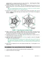
Page 26: ...GURE 1 Torque Sequence for Bonnet Screws 20 Apply a small amount of CHRISTO LUBE 129 to the top surface of the Bonnet the surface around the square of the Drive Screw then slip the Knob 23 into positi...

Page 27: ...he Adjusting Spring 4 Slowly open and close the Manifold Valve two or three times to remove contamination that may cause malfunctions Leave the Manifold Valve closed a If no flow comes through the Reg...

Page 28: ...corrective action information 9 EST4 ESL4 ELC4 LEAK TEST When only LP Gauge is present a With the Regulator set at A PSIG use a liquid leak detector to check for external leaks around all ports caps v...

Page 29: ...y mated into the square in the Adjusting Knob c Outlet Connection plugged Inspect and clear the Outlet Connection of any debris d Broken Adjusting Spring Replace the Adjusting Spring e Broken Seat Ste...

Page 30: ...ces Clean seating surfaces and or replace Seat Assembly 8 With the cylinder valve closed the High Pressure Gauge indicator drops and there is no immediate increase in pressure indicated on the Low Pre...

Page 31: ...www thermadyne com Thermadyne Industries Inc 2011 WOR L D H E A DQUARTE RS 1 605 2 S w in gley R i dg e Ro a d Suit e 3 0 0 S t L ouis Mi ss o uri 6 3 0 1 7 U S A A Global Cutting Welding Market Lead...

Reviews: