background image

53

PRE-OPERATION CHECK

Check Engine Oil Level

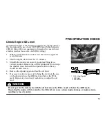
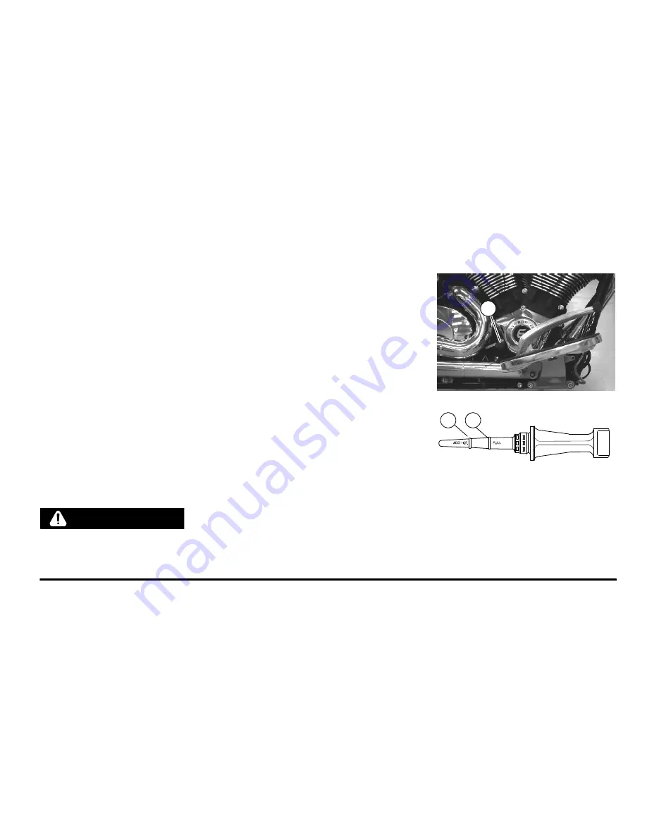
A dipstick attached to the oil fill cap registers the engine oil level.

We recommend the use of only VICTORY brand Semi-Synthetic

20W-40 Motor Oil or an equivalent oil designed for use with wet

clutches (such as those with a JASO MA rating).
1. With the transmission in neutral, start and run the engine for

several minutes.

2. Shut the engine off and wait for 3-5 minutes.
3. Straddle the motorcycle on level ground and bring it to a

vertical position. Remove the oil fill cap/dipstick (1) and wipe

the dipstick clean. Reinstall the dipstick and turn the cap

clockwise until it seats.

4. Remove the dipstick again and read the oil level.
5. If necessary, add or remove oil to bring the level into the area

on the dipstick above the ADD mark and below the FULL

mark. Repeat step 1 and step 2 each time you adjust the oil

level.

Do not operate the motorcycle with the oil level above the FULL mark or below the ADD mark.

Operating the engine with too much or too little oil can cause serious engine damage or engine seizure,

resulting in loss of control.

WARNING

1

2

3

2. ADD Mark
3. FULL Mark

1. Oil Fill Cap/Dipstick

Summary of Contents for 2009 KINGPIN

Page 1: ......

Page 2: ......

Page 3: ...This product contains or emits chemicals known to the state of California to cause cancer and birth defects or other reproductive harm California Proposition 65 Warning...

Page 4: ...created a web site just for YOU S Technical tips S New product introductions S Event schedules S Parts and Service Manual information S Exciting details about The Way Out Check it out www victory usa...

Page 5: ......

Page 6: ...ustries Inc 2100 Highway 55 Medina Minnesota 55340 9800 Phone 1 888 704 5290 CopyrightE 2007 Polaris Sales Inc All rights reserved POLARIS POLARIS THE WAY OUT FREEDOM VEGAS KINGPIN and VICTORY MOTORCY...

Page 7: ...f the motorcycle after you ve read this manual please contact an authorized VICTORY dealer To locate the nearest authorized VICTORY dealer call 1 800 POLARIS and provide the area code or zip code of y...

Page 8: ...ORTING SAFETY DEFECTS 30 COMPONENT IDENTIFICATION 31 INSTRUMENTS FEATURES AND CONTROLS 39 PRE OPERATION CHECK 50 OPERATION 67 MAINTENANCE 81 MAINTENANCE RECORD 86 CLEANING 144 STORAGE 150 WARRANTIES 1...

Page 9: ...e safety section beginning on page 5 Understand and follow the procedures in your owner s manual to keep your VICTORY motorcycle in top condition on the road or in storage Bring the manual with you wh...

Page 10: ...ual The safety alert symbol indicates a potential for personal injury to you or others The safety alert warning indicates a potential hazard that could result in serious injury or death WARNING The sa...

Page 11: ...e operating the motorcycle S Your ability to safely operate the motorcycle depends on your judgment and your use of safe riding habits Take a rider education course from the Motorcycle Safety Foundati...

Page 12: ...rating see the specifications section beginning on page 164 or the certification label on the steering head Riding off road or carrying weight exceeding the maximum weight rating can make handling di...

Page 13: ...lls and limits and ride within them S Allow only licensed experienced operators to ride your motorcycle and then only after they have become familiar with its controls and operation S Do not ride when...

Page 14: ...n the handlebars and your feet on the footrests S Obey the speed limit and adjust your speed and riding technique based on road weather and traffic conditions As you travel faster the influence of all...

Page 15: ...ac tices The rear brake provides 40 of the motorcycle s stopping power at most Consider road conditions before applying the brakes When the road is wet or rough or contains loose or other slippery sub...

Page 16: ...he seat strap with both hands and to keep both feet on the passenger footrests Do not carry a passenger who cannot place both feet firmly on the passenger footrests A passenger who is not holding on p...

Page 17: ...irborne particles and objects S You and your passenger should wear bright or light colored and or reflective clothing to improve visibility to oth er motorists A motorist s failure to see or recognize...

Page 18: ...an reduce stability and handling and could cause loss of control Refer to the specifications section of this manual beginning on page 164 or the certification label on your motorcycle s steering head...

Page 19: ...argo saddlebags at capacity 14 lbs 6 kg Gross Vehicle Weight Rating 1151 lbs 522 kg Operator with recommended riding apparel 230 lbs 104 kg Passenger with recommended riding apparel passenger models 1...

Page 20: ...apacity of all fluids 769 lbs 349 kg KINGPIN TOUR with cargo Cargo top box at capacity 20 lbs 9 kg with cargo Gross Vehicle Weight Rating Cargo saddlebags at capacity 14 lbs 6 kg Gross Vehicle Weight...

Page 21: ...rom riding Uneven weight distribution or accessories or cargo that shift suddenly while you re riding can make the motorcycle hard to handle and result in loss of control S Do not attach large or heav...

Page 22: ...ng or buffeting effects of wind can make the motorcycle unstable and cause loss of control S Distribute weight evenly in each of the saddlebags S Do not exceed the maximum cargo weight limit of the sa...

Page 23: ...cycle When leaving the motorcycle unattended turn the engine off and remove the ignition key See page 79 Park the motorcycle where people are not likely to touch the hot engine or exhaust system or pl...

Page 24: ...motorcycle leans to one side Gasoline is a fire hazard and it can also damage the motorcycle s finish S Place the transmission in neutral S Do not restrain the motorcycle using the handlebars Loosen t...

Page 25: ...or your ability to operate controls Displace you from your normal riding position Obscure lights or reflectors S Bulky or large accessories can cause instability due to the lifting or buffeting effec...

Page 26: ...are sparks or open flame Gasoline and gasoline vapors are poisonous and can cause severe injury Do not swallow gasoline inhale gasoline vapors or spill gasoline on yourself or your clothes If you swa...

Page 27: ...ance Inspect tires regularly and replace them if they re worn or damaged Use only an approved replacement tire and see the VICTORY Service Manual or your authorized VICTORY Dealer for tire replacement...

Page 28: ...must be clean clearly visible in all conditions and installed in a position specified by law S Each fastener used in the motorcycle meets our quality specifications for strength finish and type When...

Page 29: ...B C E D B A D C E A 24 SAFETY Location of Safety and Vehicle Information Labels All Models See page 25 for decal type and description...

Page 30: ...ls All Models Location A FUEL WARNING Location B MANUFACTURING INFORMATION Information varies by model Location C NOISE EMISSION Location E ENGINE I D on right rear crankcase half Location D TIRE INFO...

Page 31: ...26 SAFETY Location of Safety and Vehicle Information Labels All Models See page 27 for decal type and description F...

Page 32: ...27 SAFETY Location of Safety and Vehicle Information Labels All Models Location F FUSE and RELAY LOCATION Under right side cover on side of fuse box cover FUSE BOX REMOVAL on base of fuse box...

Page 33: ...28 SAFETY Location of Safety and Vehicle Information Labels All Models See page 29 for decal type and description I I H G G H...

Page 34: ...tion G TIRE SAFETY Location H EMISSION CONTROL INFORMATION Canada Models 49 State Models Location I PATENT NOTICE LH Rear of subframe down tube Information varies by model Catalyst Models Only Locatio...

Page 35: ...tion and if it finds that a safety defect exists in a group of vehicles it may order a recall and remedy campaign However NHTSA cannot become involved in individual problems between you your dealer or...

Page 36: ...AS Models 1 Speedometer 2 Front Brake Fluid Reservoir 3 Right Mirror 4 Throttle Control Grip 5 Front Brake Lever 6 Right Handlebar Switch 7 Indicator Lamps 8 Fuel Cap 9 Left Handlebar Switch 10 Clutch...

Page 37: ...ver 9 Taillight 10 Rear Turn Signal 11 Rear Axle Adjuster 1 each side 12 Rear Brake Caliper 13 Passenger s Foot Rest passenger models 14 Evaporative Canister California Models 15 Engine Oil Filter 16...

Page 38: ...sorber access through RH side cover 7 Front Turn Signal 8 Front Fork 9 Rear Brake Pedal 10 Operator Foot Rest 11 Engine Oil Fill Cap Dipstick 12 Rear Brake Fluid Reservoir under side cover 13 Drive Sp...

Page 39: ...Area KINGPIN Models 1 Indicator Lamps 2 Front Brake Fluid Reservoir 3 Right Handlebar Switch 4 Right Mirror 5 Throttle Control Grip 6 Throttle Cables 7 Fuel Cap 8 Left Mirror 9 Left Handlebar Switch...

Page 40: ...ry under side cover 10 Taillight 11 Rear Turn Signal 12 Rear Axle Adjuster 1 each side 13 Rear Brake Caliper 14 Passenger s Foot Rest passenger models 15 Evaporative Canister California Models 16 Oil...

Page 41: ...Absorber access through RH side cover 5 Side Cover 6 Engine Oil Fill Cap Dipstick 7 Front Brake Lever 8 Front Turn Signal 9 Horn 10 Front Fork 11 Rear Brake Pedal 12 Operator s Foot Rest 13 Rear Brake...

Page 42: ...or to order replacement parts SAE assigned World Manufacturing Identifier Chassis A VEGAS 8 BALL B NESS JACKPOT C KINGPIN D NESS SIGNATURE SERIES KINGPIN E NESS SIGNATURE SERIES VEGAS G VEGAS H HAMMER...

Page 43: ...portion of the right crankcase behind the rear cylinder You may need the engine identification number to title register license or insure the motorcycle or to order replacement parts Ignition Key Numb...

Page 44: ...cal circuits are energized and the ignition key cannot be removed The headlamp taillight and instrument lights illuminate With the engine stop run switch set to the RUN position see page 46 you can st...

Page 45: ...ortion of the speedometer Trip Odometer A trip odometer is included on the speedometer The trip odometer shows total miles traveled since the trip odometer was reset You can use the trip odometer to c...

Page 46: ...RPM A red line on the gauge indicates maximum safe engine RPM With tachometer installed the trip odometer reset button 2 is located on the instrument mounting plate See page 40 Do not operate the eng...

Page 47: ...any time the ignition switch is in the ON position and the engine control module sensors report abnormal sensor or engine operation The check engine indicator will continue to illuminate as long as t...

Page 48: ...the engine off immediately The low oil pressure indicator also illuminates when the ignition switch is in the ON position and the engine is not running This demonstrates that the indicator is functio...

Page 49: ...he flashers Headlamp High Low Beam Switch The headlamp high low beam switch toggles the headlamp between high beam low beam and momentary passing beam To activate the high beam press the upper portion...

Page 50: ...s below 15 mph cancellation will occur shortly after speed again reaches 15 mph The 15mph speed is approximate Turn Signal Switch Momentary Feature When passing a vehicle or when changing lanes the op...

Page 51: ...rgency conditions Starter Button The starter button works only when the engine stop run switch is in the RUN position and the transmission is in neutral or the clutch is disengaged To engage the engin...

Page 52: ...the gear shift pedal To shift to a higher gear lift up on the gear shift pedal For proper gear shifting procedure see Shifting Gears pages 73 and 74 Rear Brake Pedal The rear brake pedal 2 is on the...

Page 53: ...e Fueling and Fill Height page 70 Side Covers Your motorcycle is equipped with two removable side covers Remove the left side cover to access the battery Remove the right side cover to access the fuse...

Page 54: ...ard the sidestand until the sidestand firmly supports the motorcycle To retract the sidestand lean the motorcycle away from the sidestand until the motorcycle is fully upright Swing the sidestand back...

Page 55: ...ional service information in the maintenance section of this manual in the VICTORY Service Manual or from an authorized VICTORY dealer During the pre operation check you might use products that are po...

Page 56: ...the transmission is in neutral the neutral indicator should remain illuminated Headlamp Check the headlamp to see that it is on Set the headlamp switch to the high beam position The headlamp brightnes...

Page 57: ...the top of the switch to activate the emergency flashers All four turn signals and the turn signal indicator light on the panel should flash Press the bottom of the switch to cancel the flashers The t...

Page 58: ...a vertical position Remove the oil fill cap dipstick 1 and wipe the dipstick clean Reinstall the dipstick and turn the cap clockwise until it seats 4 Remove the dipstick again and read the oil level...

Page 59: ...ext fuel stop and plan accordingly to avoid running out of fuel Fuel Hose Rail and Connections Inspect the fuel hoses for cracks or damage Inspect the hose connection at the fuel tank and at the fuel...

Page 60: ...ure table on page 127 or to the decal on the motorcycle Tire Condition Inspect the tire sidewalls road contact surface and tread base for cuts punctures and cracking Replace damaged tires immediately...

Page 61: ...ach distance to the hand grip is adjustable To adjust pull and hold the lever away from the grip S To increase reach distance turn the adjuster to align a lower number to the indicator mark on the lev...

Page 62: ...with the front wheel straight forward Do not use the side stand Position the handlebars so that the brake fluid reservoir is level 2 View the brake fluid through the sight glass The fluid should be cl...

Page 63: ...of pedal travel If the brake pedal travels too far before beginning to engage the brake see the VICTORY Service Manual or contact an authorized VICTORY dealer for service The brake pedal should be ad...

Page 64: ...motorcycle and bring it to a vertical position 2 View the brake fluid through the reservoir The fluid should be clear and at a level between minimum MIN and maximum MAX marks on the side of the reserv...

Page 65: ...luid Tighten any leaking connections and replace components as necessary Refer to the Victory Service Manual for torque values of fasteners or contact your Victory dealer Brake Pads Inspect front 1 an...

Page 66: ...ttle control grip It should rotate smoothly from its rest position to its completely open position and back again It should return to its rest position quickly when released 2 Throttle freeplay is the...

Page 67: ...utch lever movement from the rest position to the point of cable resistance Freeplay gap should be 02 06 inch 0 5 1 5 mm Measure the gap between the clutch lever and the lever housing 3 Adjust clutch...

Page 68: ...eel straight forward Do not use the side stand Position the handlebars so that the clutch fluid reservoir is level 2 View the fluid level through the sight glass The fluid should be clear and at a lev...

Page 69: ...ate smoothly and quietly 3 Place the motorcycle on the sidestand and inspect the front forks Make sure there is no fork oil present on the fork tube or around the fork seal Check Steering Straddle the...

Page 70: ...ect amount of suspension travel and ground clearance see page 100 Inadequate ground clearance could allow components to come into contact with the ground causing loss of control WARNING Check Drive Be...

Page 71: ...the sidestand rubber pad 2 and make sure it s firmly attached to the sidestand Check the wear indicator 3 on the leading edge of the sidestand rubber pad Replace the pad if worn beyond the WEAR LIMIT...

Page 72: ...or best performance and longevity Important areas covered include S Engine Break in Period S Fueling and Fill Height S Starting the Engine S Shifting Gears S Accelerating S Braking S Stopping the Engi...

Page 73: ...oid prolonged full throttle operation or any condition that creates excessive engine heat Caution 0 90 miles 0 145 kilometers S Do not operate the motorcycle for extended periods of time at throttle p...

Page 74: ...orcycle requires and should be performed by an authorized VICTO RY dealer Initial maintenance service must include inspection adjustments tightening of fasteners and engine oil and filter change Perfo...

Page 75: ...ust system This could cause a fire Immediately wipe or rinse with water gasoline spilled on any part of the motorcycle or the surrounding area Do not fill the fuel tank above the fuel filler insert Ov...

Page 76: ...ngine The VICTORY motorcycle has a starter interlock system The engine can be started only when the transmission is in neutral or when the transmission is in gear and the clutch is disengaged clutch l...

Page 77: ...en press and hold the starter button again Hold the starter button for as short a time as possible to minimize battery drain and do not push the starter button for more than 10 seconds at any one time...

Page 78: ...ission type for your model TOE SHIFT PEDAL Shift to a higher gear by lifting the front of the pedal with your toe To shift to a lower gear depress the pedal with your toe HEEL TOE SHIFT PEDAL Shift to...

Page 79: ...ee Recommended Shift Points on page 75 7 With a quick motion simultaneously close the throttle completely and disengage the clutch 8 Raise the shift pedal with your toe or depress it with your heel un...

Page 80: ...le passing over such surfaces release the clutch lever very gradually Downshifting in a curve may cause the rear wheel to lose traction Downshift before entering a curve WARNING Recommended Shift Poin...

Page 81: ...ding to the instructions in Shifting Gears page 73 The more quickly you open the throttle the more quickly the motorcycle accelerates Abrupt acceleration can cause your body to shift suddenly toward t...

Page 82: ...that either wheel stops rotating Leave sufficient distance so you can apply the brakes gradually if you need to stop Do not apply either brake so strongly that the wheel stops rotating This may cause...

Page 83: ...ove the ignition key NOTE Idle air control IAC noise is a normal engine management calibration process that occurs each time the engine stop run switch is put into the STOP position or when the key is...

Page 84: ...the motorcycle Take the key with you If you must park on a slope point the motorcycle toward the top of the slope Put the transmission in gear and park the motorcycle so that it is stable when it rest...

Page 85: ...e sidestand from sinking into the asphalt Caution A hot engine or hot exhaust pipes can be hazardous The engine and exhaust pipes are hot for some time after the engine is stopped Touching the engine...

Page 86: ...the entire procedure in this section of the Owner s Manual Choose a flat firm surface for servicing the motorcycle Make sure you have the time tools and expertise to complete a procedure properly Dur...

Page 87: ...mance for its entire service life Periodic Maintenance Intervals Use the following table to determine how often you should perform maintenance on various components For additional information on maint...

Page 88: ...I I I I I I R I I I I I I I I Clutch Lever 111 I I L I L I L I L I L Control Cables 116 I I L I L I L I L I L Crankcase Ventilation System 107 I I I I I I I I I I I Drive Belt 92 I I I I I I I I I I...

Page 89: ...porative Emission Control System California Only 107 I I I I I I I I I I I Fasteners 142 I I I I I I I I I I I Front Brake Lever 117 I I L I L I L I L I L Front Fork Oil 105 I I I R I I R I I R I Fron...

Page 90: ...I I R Road Test 142 P P P P P P P P P P P P P P P P P P P P P Sidestand 66 I I L I L I L I L I L Sidestand Rubber Pad 66 I I I I I I I I I I I I I I I I I I I I I Spark Plugs 129 I I I I I I R I I I I...

Page 91: ...86 MAINTENANCE MAINTENANCE RECORD MAINTENANCE PERFORMED MILES KM NOTES PERFORMED BY...

Page 92: ...87 MAINTENANCE MAINTENANCE RECORD MAINTENANCE PERFORMED MILES KM NOTES PERFORMED BY...

Page 93: ...r flammable materials WARNING 1 Start and run the engine until it reaches normal operating temperature Stop the engine 2 Securely support the motorcycle on the sidestand 3 Place a drain pan under the...

Page 94: ...and Semi Synthetic 20W 40 Motor Oil or an equivalent oil designed for use with wet clutches such as those with a JASO MA rating 10 Reinstall the oil fill cap and then start and run the engine until it...

Page 95: ...turn the cap clockwise until it seats 4 Remove the dipstick again and note the oil level 5 If necessary add or remove oil to bring the level into the area on the dipstick above the ADD mark and below...

Page 96: ...er and air filter element using the universal tool provided under the left side cover see page 142 2 To remove debris from the element use low pressure air and blow from the rear forward Wear face pro...

Page 97: ...low the belt to cool down to ambient temperature before measuring belt tension Replace drive belt and both sprockets as a set if drive belt has over 5 000 miles 8 000 km of service at the time of dama...

Page 98: ...ow the instructions provided with the meter Required Data Required Data Span 658 3mm Tension new belt 50 6 Hz Belt width 28mm Tension after 500 miles 48 3 Hz Belt mass constant 7 9 Drive Belt Wear Ana...

Page 99: ...ely under the frame Care should be taken to be sure the motorcycle will not tip or fall while elevated Severe personal injury or death may occur if the motorcycle tips or falls WARNING 2 Position the...

Page 100: ...the zero force position and the 10 lbs force position you recorded Refer to the chart on page 93 for belt specifications 7 Belt deflection must be measured and adjusted with the belt at the tightest...

Page 101: ...rear an equal amount if wheel is in alignment or turn each adjuster as needed to align the wheel and achieve proper tension See Check Drive Belt Tension page 92 Use an 8mm hex tool on screw style adju...

Page 102: ...opriate motorcycle lift or a block of wood or steel placed securely under the frame 3 The axle adjusters or plates 1 are stamped with marks 2 that are used as a reference to ensure proper wheel alignm...

Page 103: ...On both styles Turn the screw or nut IN clockwise to draw the axle back or OUT counterclockwise to allow the axle to move forward NOTE If adjuster screws or nuts are turned OUT counterclockwise push...

Page 104: ...nd alignment to be sure it is correct after tightening the axle 10 If alignment is incorrect repeat steps 4 8 11 Pump rear brake pedal several times to reset brake pad distance 12 Carefully lower the...

Page 105: ...2 Load the motorcycle with all cargo you intend to carry With the motorcycle in the upright position sit on the operator s seat with your riding gear on If you plan on carrying a passenger have them s...

Page 106: ...pectRear Shock Absorber Preload Ride Height Motorcycle in upright position Floor Frame Cradle Weight of Operator Passenger Gear in position Operator Passenger Gear Measure from floor to rearmost flat...

Page 107: ...e sure that the rear brake fluid reservoir cap is secured to prevent fluid loss page 122 3 Remove three 10mm bolts 1 holding the fuse box bracket to chassis 4 Remove the on board diagnostics connector...

Page 108: ...rive belt 9 Adjust shock absorber preload by rotating adjuster nut clockwise as viewed from the top of shock absorber to INCREASE the ride height measurement firm and counterclockwise to DECREASE the...

Page 109: ...wheel side to side NOTE If there is movement at the rear axle inspect the wheel bearings and rear axle see the VICTORY Service Manual or an authorized VICTORY dealer If there is movement at the front...

Page 110: ...uld operate smoothly and quietly 3 Place the motorcycle on the sidestand and inspect the front forks Make sure there is no fork oil present on the fork tube 1 or around the fork seal 2 4 Clean the for...

Page 111: ...front to back NOTE If there is front to back movement at the steering head the steering head bearings should be inspected lubricated and adjusted see the VICTORY Service Manual or an authorized VICTO...

Page 112: ...mage Inspect the hose connection at the air cleaner and at the crankcase for dampness or stains from leaking Evaporative Emission Control System California models only Visually inspect all evaporative...

Page 113: ...efully remove the fuel tank 8 To reinstall the fuel tank reverse the removal steps routing fuel supply hose to the right of breather hose 9 Reinstall the fuel line fitting to the fuel rail by sliding...

Page 114: ...hen released 2 Throttle freeplay is the amount of throttle control grip movement from the rest position to the point of cable resistance Freeplay should be 2 4 mm Adjust throttle freeplay if necessary...

Page 115: ...5 To adjust the closing cable the one toward rear of motorcycle move the throttle grip back and forth constantly and turn adjuster out slowly just until freeplay is removed Turn the adjuster back in o...

Page 116: ...the amount of clutch lever movement from the rest position to the point of cable resistance Freeplay gap should be 0 5 1 5mm Measure the gap between the clutch lever and the lever housing Adjust clut...

Page 117: ...in or out until the clutch lever freeplay 4 is 0 5 1 5mm 5 Tighten the adjuster lock nut securely while holding cable 6 Reinstall right side cover 7 Verify that the safety switch activates so the mot...

Page 118: ...wheel straight forward Do not use the side stand Position the handlebars so that the clutch fluid reservoir is level 2 View the fluid level through the sight glass The fluid should be clear and at a...

Page 119: ...clutch while the reservoir cover is removed Fluid could overflow from the reservoir and cause air to enter the fluid system Air in the fluid system could cause the clutch to malfunction Use DOT4 brake...

Page 120: ...pivot screw with VICTORY Moly Assembly Grease or Victory All Purpose grease 6 Reconnect the clutch cable Reinstall the lever pivot screw and nut Hold pivot screw down and torque nut to 40 in lbs 5 Nm...

Page 121: ...adjuster of the cable to be lubricated and disconnect one end of the cable 2 Lubricate the cable and the inside of the cable housing with VICTORY Cable Lube PN 2872861 or a commercially available cabl...

Page 122: ...ly and smoothly and should return to its rest position quickly when released You should feel a firm resistance in the lever within the first 3 4 inch 19 mm of lever travel If the brake lever travels t...

Page 123: ...s is critical for proper brake function 3 Remove any old grease and dirt from the brake lever and housing 4 Lubricate the brake lever and lever pivot pin with VICTORY All Purpose Grease or equivalent...

Page 124: ...d with the front wheel straight forward Do not use the side stand Position the handlebars so that the brake fluid reservoir is level 2 View the brake fluid through the sight glass 1 The fluid should b...

Page 125: ...the system seals resulting in the brakes malfunctioning WARNING 1 Straddle the motorcycle and bring it to a vertical position Turn the handlebars until the reservoir is horizontal 2 Wipe the area aro...

Page 126: ...he brake see the VICTORY Service Manual or contact an authorized VICTORY dealer for service The brake pedal should be adjusted so that in the relaxed position with the master cylinder piston positione...

Page 127: ...id if necessary Add Rear Brake Fluid Do not operate the rear brake while its reservoir cover is removed Fluid could overflow from the reservoir and cause air to enter the fluid system Air in the brake...

Page 128: ...e brake fluid container with a clean cloth 5 Remove the reservoir cover and gasket Brake fluid attacks painted surfaces and plastic parts Always clean spilled brake fluid immediately with plenty of wa...

Page 129: ...place brake pads when wear lines 3 are no longer visible or when pad thickness reaches 1 5 mm The shielded pad must be installed on the non piston side of the caliper If the brake pads require replace...

Page 130: ...has worn to the minimum thickness at the thinnest point or if the disc is damaged contact your VICTORY dealer for replacement Check Brake Hoses and Connections Inspect all brake hoses and connections...

Page 131: ...y 3 Tighten the linkage rod locknuts 4 Check the gear shift pedal height Do not remove and reposition the shift arm on the shift shaft to adjust gear shift pedal height A 90_ 5_ angle between the shif...

Page 132: ...er the left side cover of the motorcycle Tire Pressure Table VEGAS VEGAS 8 BALL VEGAS LOW Up to 200 lbs 91 kg load 200 465 lbs 91 211 kg load FRONT Dunlop Elite 3 90 90 21 54H 36 psi 248 KPa 38 psi 26...

Page 133: ...ORY dealer Check Tread Depth Raised areas at the base of the tread known as wear bars act as easily visible tread depth indicators When the road contact surface has worn to the top of the wear bars re...

Page 134: ...the other see the VICTORY Service Manual or an authorized VICTORY dealer for assistance 1 Make sure the engine is at room temperature 2 Disconnect the spark plug wire by pulling upward on the spark p...

Page 135: ...plugs are in good condition and are not due for replacement you can clean them with a non metallic stiff bristle brush set the gap and reinstall them Replace spark plugs at the recommended intervals A...

Page 136: ...er Check Exhaust System Check the exhaust system for stains from leaking exhaust gasses Replace exhaust gaskets if necessary see the VICTORY Service Manual or an authorized VICTORY dealer Check all ex...

Page 137: ...tion causing loss of control WARNING 1 Remove the right and left side covers 2 Remove the fuse box from the bracket see page 27 3 Remove the right seat screw Remove the left seat screw 4 Lift the rear...

Page 138: ...s and get prompt medical attention WARNING The motorcycle uses a permanently sealed maintenance free battery Do not remove the battery cap strip for any reason Keep the battery connections clean and t...

Page 139: ...cover 2 Disconnect the negative battery cables cable ends are exposed 3 Disconnect the positive cables cable ends are covered with a red boot Disconnecting the positive cable first can produce an elec...

Page 140: ...thin film of dielectric grease to the posts and cable connectors 2 Following the charger manufacturer s instructions use a battery charger designed for use with 12 volt batteries The charger should h...

Page 141: ...ositive battery cables tighten securely and install the red boot 4 Connect the negative cables tighten securely Be sure cables have adequate side cover clearance Connecting the negative cable first ca...

Page 142: ...cover 3 Remove the damaged fuse from the fuse box and seat the new fuse firmly in its place A spare 15 amp fuse is located in the fuse box 4 Reinstall the fuse box cover with the double cutout toward...

Page 143: ...ther right of center than the high beam U S Canada 1 Check and adjust the tire pressure page 127 2 Verify rear suspension ride height measurement is at specification see page 101 before adjusting head...

Page 144: ...lt 2 Aim headlight and hold in position while tightening nut Torque 35 ft lbs 47 5 Nm 6 To adjust the lamp horizontally loosen the nut 3 aim headlight and hold in position while tightening nut Torque...

Page 145: ...t the motorcycle Caution Inspect Sidestand Pad Straddle the motorcycle and bring it to a vertical position Move the sidestand 1 to its stored up position then to its fully extended down position and b...

Page 146: ...e nut and remove the sidestand pivot bolt and sidestand return spring 4 Wipe any old grease and dirt from the sidestand frame and pivot bolt 5 Lubricate the sidestand the pivot bolt and the ends of sp...

Page 147: ...nd can be used to service the following items Oil Drain Plug Handlebar Adjustment Turn Signal Bulb Air Filter Passenger Seat Indicator Bulbs Headlight Bulb Accessory Saddlebag Windshield and Driver s...

Page 148: ...143 MAINTENANCE NOTES...

Page 149: ...th salty or polluted air wash your motorcycle frequently Proper cleaning requires washing and drying the motorcycle and then applying wax polish and protectants to extend the service life and appearan...

Page 150: ...those found at car washes Excessive water pressure may allow water to seep in and deteriorate wheel bearings brake caliper assemblies brake master cylinders electrical connectors steering head bearin...

Page 151: ...to remove by applying gentle pressure using the warm water and mild detergent mixture you may need to use a special cleaner Choose a cleaner designed for use on the type of surface you plan to clean...

Page 152: ...wax polish or protectants After washing and drying the motorcycle to help extend the life and appearance of its components S Wax painted surfaces Avoid cleaning waxing compounds as they may contain a...

Page 153: ...provide plenty of soapy water for washing and keep the cloth or sponge clean by rinsing it frequently S Minor scratches may be removed with a quality plastic polishing compound Follow the manufacturer...

Page 154: ...drier climates will require more frequent conditioning To retain the beauty and character of your leather saddlebags please follow these steps 1 Vacuum or blow any loose dust or dirt from the saddleba...

Page 155: ...aging This section includes instructions for preparing the motorcycle for storage maintaining it during storage and removing it from storage Storage Area Preparation Choose a dry well ventilated stora...

Page 156: ...lean Plus or other gasoline stabilizer fill the fuel tank only to the top of the filler insert 2 Ride the motorcycle or start and run the engine for 15 minutes in a well ventilated area to pass the st...

Page 157: ...of mild detergent and warm water 4 Store the battery in a dry location that maintains a temperature of 32_ to 90_F 0_ to 32_C 5 While in storage fully charge the battery once a month see page 135 Par...

Page 158: ...e change the engine oil and filter see page 88 beginning with step 4 During storage temperature and humidity changes can cause condensation to form in the crankcase and mix with engine oil Running the...

Page 159: ...t which conducts exhaust gases S Removal or puncturing of any part of the intake system S Lack of proper maintenance S Replacing any moving part of the vehicle or parts of the exhaust or intake system...

Page 160: ...ime listed below provided there has been no abuse neglect or improper maintenance of your motorcycle Your emission control system may include parts such as the fuel injection system the ignition syste...

Page 161: ...El Monte CA 91734 8001 VICTORY Motorcycle Division Polaris Sales Inc Limited Warranty on Emission Control System VICTORY Motorcycle Division Polaris Sales Inc hereinafter VICTORY warrants that each n...

Page 162: ...condensers and spark plugs if failure occurs prior to the first scheduled replacement and hoses clamps fittings and tubing used directly in these parts Since emission related parts may vary from model...

Page 163: ...nts improperly installed 4 use of replacement parts or accessories not conforming to VICTORY specifications which adversely affect performance and or 5 use in competitive racing or related events B In...

Page 164: ...SE THE VICTO RY MOTORCYCLE FOR ANY PURPOSE SOME STATES DO NOT ALLOW THE EXCLUSION OR LIMITATION OF ANY INCIDENTAL OR CONSEQUENTIAL DAMAGES SO THE ABOVE LIMITATIONS MAY NOT APPLY TO YOU B NO EXPRESS EM...

Page 165: ...performance and durability may be used in the performance of any maintenance or repairs How ever VICTORY is not liable for these parts The owner is responsible for the performance of all required main...

Page 166: ...leted by your dealer and submitted to VICTORY Motorcycle Division Polaris Sales Inc within ten days Upon receipt of this registration VICTORY Motorcycle Division Polaris Sales Inc will record the regi...

Page 167: ...explosions or any other cause beyond VICTORY Motorcycle Division Polaris Sales Inc control This warranty does not cover the use of unauthorized lubricants chemicals or fuels that are not compatible wi...

Page 168: ...CTORY Motorcycle Servicing Dealer When requesting warranty service you must present your copy of the Warranty Registration form to the dealer THE COST OF TRANSPORTATION TO AND FROM THE DEALER IS YOUR...

Page 169: ...2 lbs 296 kg VEGAS 8 BALL 651 lbs 295 kg VEGAS LOW 676 lbs 307 kg KINGPIN 741 lbs 336 kg KINGPIN TOUR 670 lbs 304 kg KINGPIN 8 BALL Wet Weight 686 lbs 311 kg VEGAS 680 lbs 308 kg VEGAS 8 BALL 679 lbs...

Page 170: ...Electronic Fuel Injection 45 mm Exhaust System Dual Staggered Dual Staggered Lubrication System Wet Sump Wet Sump Spark Plug Gap NGK DCPR6E 031 035 inch 0 8 0 9 mm NGK DCPR6E 031 035 inch 0 8 0 9 mm C...

Page 171: ...nstant Mesh 8 BALL Primary Drive Gear With Torque Compensator Gear With Torque Compensator Primary Reduction Ratio 1 5 1 1 5 1 Gear Shift Pattern 1 Down 5 Up 1 Down 5 Up Internal Gear Ratios 1st 3 15...

Page 172: ...55 B18 74V Electrical Alternator 38 Amp Max Output 38 Amp Max Output Battery 12 Volts 18 Amp Hour 12 Volts 18 Amp Hour Lights and Fuses Fuses Engine ECM 15 amp 15 amp Fuel Pump 10 amp 10 amp Headlamp...

Page 173: ...oline containing up to 15 Methyl Tertiary Butyl Ether MTBE can be used Gasoline containing up to 10 Ethanol can be used Gasoline that has been Reformulated or Oxygenated can be used Engine Oil Specifi...

Page 174: ...ead see page 37 Engine Identification Number ________________________________________ Located on crankcase to right of oil filter see page 38 Ignition Key Number ______________________________________...

Page 175: ...125 Brake Fluid 122 Brake Fluid Level 57 59 119 122 Brake Fluid Rear 123 Brake Hoses 125 Brake Lever 46 Brake Lever Lubrication 118 Brake Lever Movement 56 117 Brake Pads 60 124 Brake Pedal 47 Brake P...

Page 176: ...Axle 106 Front Brake Lever 46 Front Brake Lever Movement 56 Fuel 21 Fuel Cap 48 Fuel Components 54 Fuel Filter Replacement 108 Fuel Hose 54 Fuel Hose Rail and Connections 54 107 Fuel Level 54 Fuel Sp...

Page 177: ...O Odometer 40 Oil 88 90 Oil Change 88 89 Oil Filter 88 89 Oil Filter Change 88 89 Oil Level 53 89 90 Oil Specifications 168 Overdrive Indicator Lamp 41 P Park Position P 39 Parking the Motorcycle 18 7...

Page 178: ...on Rear 65 101 104 Swing Arm 104 Symbols and Terms 5 T Tachometer 41 Taillight Brake Light 51 Test Drive 142 Throttle 109 110 Throttle Control Cables 61 109 Throttle Control Grip 46 61 109 Throttle Fr...

Reviews: